
Declaring an interface is only half the story — this article covers the formal syntax, how the same interface connects a testbench to either a plain Verilog design or a SystemVerilog design, why traditional port-by-port connections don't scale as a design grows, how to declare an array of interface instances, and how tasks, functions, assertions, and coverage can live directly inside an interface.
10 min read | Intermediate Level
What You'll Learn
- The formal syntax for declaring an interface, and what it can contain beyond plain signals
- How the same interface connects a testbench to either a plain Verilog design, or a SystemVerilog design that accepts the interface directly as a port
- Why Verilog's traditional one-signal-at-a-time port connections get unwieldy at scale, and how an interface fixes that
- How to declare and connect an array of interface instances
- How tasks, functions, assertions, and coverage can be declared right inside an interface, alongside the signals they work with
- A parsing gotcha with interfaces that have no port list
Interface Syntax
Interface blocks are defined between interface and endinterface. Like a module, an interface can be instantiated with or without ports:
interface [name] ([port_list]);
	[list_of_signals]
endinterface
Interfaces can also have functions, tasks, variables, and parameters, making them more like a class template. They can define port directions for different modules via modport, along with testbench synchronization via clocking blocks. An interface can also contain assertions, coverage recording, and other protocol-checking elements, plus initial and always procedures and continuous assign statements.
A module cannot be instantiated inside an interface. An interface, however, can be instantiated inside a module.
Connecting an Interface to a Verilog Design
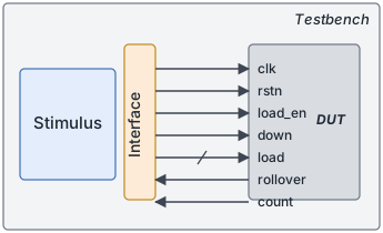
The design below is an up-down counter written in plain Verilog. It accepts a parameter deciding the counter's width, and an input load value that's loaded into the counter only when load_en is 1. It counts down when down is 1, and otherwise counts up; rollover is asserted whenever the counter sits at its maximum value (all 1s) — the point right before it would wrap back to 0 while counting up, or right after wrapping from 0 while counting down.
module counter_ud
  #(parameter WIDTH = 4)
  (
  input 					clk,
  input 					rstn,
  input wire [WIDTH-1:0]	load,
  input 					load_en,
  input 					down,
  output 					rollover,
  output reg [WIDTH-1:0]	count
);

  always @ (posedge clk or negedge rstn) begin
    if (!rstn)
   		count <= 0;
    else
      if (load_en)
        count <= load;
      else begin
      	if (down)
        	count <= count - 1;
      	else
        	count <= count + 1;
      end
  end

  assign rollover = &count;
endmodule
An interface called cnt_if is declared below with a parameterizable width for the counter signal:
interface cnt_if #(parameter WIDTH = 4) (input bit clk);
  logic 			rstn;
  logic 			load_en;
  logic [WIDTH-1:0] load;
  logic [WIDTH-1:0] count;
  logic 			down;
  logic 			rollover;
endinterface

module tb;
  reg clk;

  // TB Clock Generator used to provide the design
  // with a clock -> here half_period = 10ns => 50 MHz
  always #10 clk = ~clk;

  cnt_if 	  cnt_if0 (clk);
  counter_ud  c0 ( 	.clk 		(cnt_if0.clk),
                  	.rstn 		(cnt_if0.rstn),
                  	.load 		(cnt_if0.load),
                  	.load_en 	(cnt_if0.load_en),
                  	.down 		(cnt_if0.down),
                  	.rollover 	(cnt_if0.rollover),
                  	.count 		(cnt_if0.count));

  initial begin
    bit load_en, down;
    bit [3:0] load;

    $monitor("[%0t] down=%0b load_en=%0b load=0x%0h count=0x%0h rollover=%0b",
    	$time, cnt_if0.down, cnt_if0.load_en, cnt_if0.load, cnt_if0.count, cnt_if0.rollover);

    // Initialize testbench variables
    clk <= 0;
    cnt_if0.rstn <= 0;
    cnt_if0.load_en <= 0;
    cnt_if0.load <= 0;
    cnt_if0.down <= 0;

    // Drive design out of reset after 5 clocks
    repeat (5) @(posedge clk);
    cnt_if0.rstn <= 1;

    // Drive stimulus -> repeat 5 times
    for (int i = 0; i < 5; i++) begin

      // Drive inputs after some random delay
      int delay = $urandom_range (1,30);
      #(delay);

      // Randomize input values to be driven
      std::randomize(load, load_en, down);

      // Assign tb values to interface signals
      cnt_if0.load <= load;
      cnt_if0.load_en <= load_en;
      cnt_if0.down <= down;
    end

    // Wait for 5 clocks and finish simulation
    repeat(5) @ (posedge clk);
    $finish;
  end
endmodule
Output
ncsim> run
[0] down=0 load_en=0 load=0x0 count=0x0 rollover=0
[96] down=1 load_en=1 load=0x1 count=0x0 rollover=0
[102] down=0 load_en=0 load=0x9 count=0x0 rollover=0
[108] down=1 load_en=1 load=0x1 count=0x0 rollover=0
[110] down=1 load_en=1 load=0x1 count=0x1 rollover=0
[114] down=1 load_en=0 load=0xc count=0x1 rollover=0
[120] down=1 load_en=0 load=0x7 count=0x1 rollover=0
[130] down=1 load_en=0 load=0x7 count=0x0 rollover=0
[150] down=1 load_en=0 load=0x7 count=0xf rollover=1
[170] down=1 load_en=0 load=0x7 count=0xe rollover=0
[190] down=1 load_en=0 load=0x7 count=0xd rollover=0
Simulation complete via $finish(1) at time 210 NS + 0
Notice that even here, cnt_if0 doesn't eliminate the per-signal connection at the DUT instantiation — c0 still lists every port individually. The interface's real payoff shows up once the DUT itself is written to accept an interface handle directly, which is exactly what the next example does.
Quick Check
Q: Looking at the output log, why does rollover read 1 at [150] but 0 at [170], even though down is 1 in both rows?
Show Answer
rollover is driven by assign rollover = &count;, so it's only high when count equals all 1s. At [150], count=0xf (the maximum for this 4-bit counter), so rollover is 1. By [170], the counter has decremented to 0xe, so count is no longer all 1s and rollover drops back to 0.
Connecting an Interface to a SystemVerilog Design
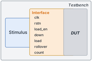
SystemVerilog allows a module to accept an interface as its entire port list, instead of individual signals. In the design below, the port list of counter_ud has been replaced with a single interface handle used to define the same design functionality:
`timescale 1ns/1ns

// This module accepts an interface object as the port list
module counter_ud  #(parameter WIDTH = 4) (cnt_if _if);
  always @ (posedge _if.clk or negedge _if.rstn) begin
    if (!_if.rstn)
   		_if.count <= 0;
    else
      if (_if.load_en)
        _if.count <= _if.load;
      else begin
        if (_if.down)
        	_if.count <= _if.count - 1;
      	else
        	_if.count <= _if.count + 1;
      end
  end

  assign _if.rollover = &_if.count;
endmodule
The design instance is passed an interface handle called cnt_if, used both to drive inputs from the testbench and to monitor outputs from the design:
// Interface definition is the same as before

module tb;
  reg clk;

  // TB Clock Generator used to provide the design
  // with a clock -> here half_period = 10ns => 50 MHz
  always #10 clk = ~clk;

  cnt_if 	  cnt_if0 (clk);

  // Note that here we just have to pass the interface handle
  // to the design instead of connecting each individual signal
  counter_ud  c0 (cnt_if0);

  // Stimulus remains the same as before
Output
ncsim> run
[0] down=0 load_en=0 load=0x0 count=0x0 rollover=0
[96] down=1 load_en=1 load=0x1 count=0x0 rollover=0
[102] down=0 load_en=0 load=0x9 count=0x0 rollover=0
[108] down=1 load_en=1 load=0x1 count=0x0 rollover=0
[110] down=1 load_en=1 load=0x1 count=0x1 rollover=0
[114] down=1 load_en=0 load=0xc count=0x1 rollover=0
[120] down=1 load_en=0 load=0x7 count=0x1 rollover=0
[130] down=1 load_en=0 load=0x7 count=0x0 rollover=0
[150] down=1 load_en=0 load=0x7 count=0xf rollover=1
[170] down=1 load_en=0 load=0x7 count=0xe rollover=0
[190] down=1 load_en=0 load=0x7 count=0xd rollover=0
Simulation complete via $finish(1) at time 210 NS + 0
Same stimulus, same output — but now c0 is instantiated with a single handle, cnt_if0, instead of seven individual port connections. That's the difference an interface-as-port makes.
What Makes It Different From Verilog?
Verilog connects between different modules through its module ports. For large designs, this connection method can become time-consuming and repetitive. Some of these ports may include signals related to bus protocols like AXI/AHB, clock and reset pins, and signals to and from RAM/memory or other peripheral devices.
Using Verilog Ports
This is the traditional way of port connection in Verilog:
module d_slave ( input  clk,
                           reset,
                           enable,
                           // Many more input signals
                     output gnt,
                            irq,
                            // Many more output signals);
   // Some design functionality
   endmodule

module d_top ( [top_level_ports] );
    reg [`NUM_SLAVES-1:0] clk;                  // Assume `NUM_SLAVES is a macro set to 2
    reg [`NUM_SLAVES-1:0] tb_reset;
    // Other declarations

	d_slave slave_0  (  .clk   (d_clk[0]),      // These connections have to be
	                  	.reset (d_reset[0]) 	// repeated for all other slave instances
	                  		...
	                  	.gnt (d_gnt[0]),
	                  	... );

	d_slave slave_1  ( ... );
	d_slave slave_2  ( ... );
endmodule
Consider a scenario where there are twelve slaves in this design. If a change is made to the d_slave module's ports, that change has to be reflected in all twelve slave instance connections in d_top as well.
Disadvantages
Some downsides of the Verilog port connection method:
- Tedious to trace, debug, and maintain
- Too easy to make or break design functionality with a small edit
- Changes in design requirements may require modifications across multiple modules
- Duplication needed across multiple modules, communication protocols, and other places
Using SystemVerilog Interface
Here, d_top simply uses the interface to connect with the slave instances, instead of repetitively declaring a connection to each signal of the slave block:
interface slave_if (input logic clk, reset);
	reg clk;
	reg reset;
	reg enable;

	reg gnt;
	// Declarations for other signals follow
endinterface

module d_slave (slave_if s_if);

	// Design functionality
	always (s_if.enable & s_if.gnt) begin 	// interface signals are accessed by the handle "s_if"
		// Some behavior
	end
endmodule

module d_top (input clk, reset);
	// Create an instance of the slave interface
	slave_if 	slave_if_inst ( .clk (clk),
	                            .reset (reset));

	d_slave 	slave_0 (.s_if (slave_if_inst));
	d_slave 	slave_1 (.s_if (slave_if_inst));
	d_slave 	slave_2 (.s_if (slave_if_inst));
endmodule
Now, if a signal in the slave interface changes, that change is automatically applied to every instance connected to it. The module port list can also have a port of interface type instead of the usual input, output, and inout.
This example connects all three d_slave instances to the same single interface instance, slave_if_inst, purely to keep the syntax comparison simple — all three slaves would end up sharing the same physical enable/gnt signals. In a real multi-slave design, each slave normally needs its own independent control signals, which means its own interface instance (or an array of interfaces, covered next) rather than one instance shared by all.
Quick Check
Q: If the d_slave module above gains a new input signal, how many places does that change need to be made using the interface approach, versus the traditional Verilog port approach with twelve slave instances?
Show Answer
With the interface, one place — add the signal to slave_if, and it's automatically available everywhere the interface is used. With traditional ports, the new signal has to be added to d_slave's port list and then to all twelve individual instance connections in d_top.
Interface Arrays
An interface can be declared as an array, the same way any other object can, letting a testbench connect to several identical design instances without writing a separate interface handle for each one. SystemVerilog Interface Array covers this in depth, including a parsing gotcha with port-less interfaces that's easy to trip over.
Tasks, Functions, Assertions, and Coverage Inside an Interface
The Interface Syntax section earlier mentioned that an interface can hold more than just signals — functions, tasks, assertions, and coverage can all live inside one too, right alongside the signals they operate on. Here's that claim demonstrated, extending the cnt_if interface from earlier in this article:
interface cnt_if #(parameter WIDTH = 4) (input bit clk);
  logic 			rstn;
  logic 			load_en;
  logic [WIDTH-1:0] load;
  logic [WIDTH-1:0] count;
  logic 			down;
  logic 			rollover;

  // A task other testbench code can call to pulse reset for a few clocks
  task automatic reset (input int cycles = 3);
    rstn <= 0;
    repeat (cycles) @ (posedge clk);
    rstn <= 1;
  endtask

  // A function other testbench code can call to check if count is at its max value
  function automatic bit is_max ();
    return &count;
  endfunction

  // A lightweight assertion: count should stay at 0 while rstn is low
  property p_reset_holds_count;
    @(posedge clk) !rstn |-> count == 0;
  endproperty
  assert property (p_reset_holds_count);

  // A minimal coverpoint tracking whether load_en was ever exercised
  covergroup cg_load_en @ (posedge clk);
    coverpoint load_en;
  endgroup
  cg_load_en cg_inst = new();

endinterface
Once declared, the task and function are called directly through the interface handle, the same way you'd access any other signal:
initial begin
  cnt_if0.reset();            // pulse reset for 3 clocks

  if (cnt_if0.is_max())
    $display("counter is at its max value");
end
Bundling a reset() task with the interface means every testbench that uses cnt_if gets the exact same reset sequence for free, instead of each one re-implementing its own version — one more way an interface centralizes logic that would otherwise be duplicated.
The assertion and covergroup declared above work exactly like they would anywhere else — declaring them inside the interface just means they travel with the signals automatically, with no separate wiring needed. SystemVerilog Assertions and SystemVerilog Covergroup and Coverpoint cover the full syntax and semantics of each in depth.
Quick Check
Q: Why put p_reset_holds_count and cg_load_en inside the interface instead of inside the testbench module that uses it?
Show Answer
Because they check and measure the interface's own signals, keeping them inside the interface means every module that instantiates cnt_if automatically gets the same checking and coverage, with nothing extra to wire up or duplicate — the same reuse benefit as the reset() task above.
Common Beginner Mistakes
Mistake #1: Omitting () when instantiating a port-less interface
As shown just above, mif m_if; fails to compile, while mif m_if(); succeeds. Why? Without the parentheses, the parser can't distinguish the statement from other kinds of declarations — always include () at instantiation, even for an interface with nothing in its own port list.
Mistake #2: Assuming one shared interface instance gives each module its own signals
Connecting multiple module instances to the same interface instance means they share the exact same physical signals. Why? If each instance needs independent control signals — its own enable, its own gnt, and so on — you need a separate interface instance per module instance, or an array of interfaces, not one instance reused everywhere.
Mistake #3: Trying to instantiate a module inside an interface
Interfaces can contain tasks, functions, variables, parameters, assertions, and coverage — but not a module instance. Why? The direction only goes one way: an interface can be instantiated inside a module, never the reverse.
Practice Exercise
Challenge: Give Each Slave Its Own Interface
Using the slave_if interface from earlier, fix the sharing problem noted above: declare an array of 3 slave_if instances instead of 1, and connect each d_slave to its own array element.
Hint
Follow the same interface_name array_name [N:0] (...) pattern covered in SystemVerilog Interface Array, then index into it per instance.
Solution
module d_top (input clk, reset);
	// One interface instance per slave, instead of one shared instance
	slave_if 	slave_if_inst [2:0] ( .clk (clk),
	                                   .reset (reset));

	d_slave 	slave_0 (.s_if (slave_if_inst[0]));
	d_slave 	slave_1 (.s_if (slave_if_inst[1]));
	d_slave 	slave_2 (.s_if (slave_if_inst[2]));
endmodule
Each d_slave now has its own independent enable/gnt signals, since each is connected to a different element of the slave_if_inst array instead of all three sharing one instance.
Summary
In this tutorial, you learned:
- An interface can contain not just signals, but tasks, functions, variables, parameters, assertions, and coverage — and can be instantiated inside a module, though never the reverse
- The same interface can connect a testbench to a plain Verilog design (still one signal at a time at the DUT instantiation) or to a SystemVerilog design that accepts the interface directly as its port list (a single handle)
- Traditional Verilog port connections require every signal change to be repeated across every module instance; an interface centralizes that in one place
- Multiple module instances connected to the same interface instance share the exact same signals — use an array of interfaces when each instance needs independent control signals
- Bundling a task, function, assertion, or coverage model inside the interface means every module that uses it gets the same behavior automatically, instead of duplicating it elsewhere
- An interface with no port list still needs
()at instantiation, or it fails to compile
Continuing the Interfaces & Modports Chapter
Continue with SystemVerilog Interface Array, SystemVerilog Interface Parameters, and Interface Bundles.
