
A register is a small piece of storage inside the processor that holds one value, such as a number being added or the address of the next array element. Registers are where almost all of a program's work happens: the processor reads its inputs from registers, computes, and writes the result back to a register, all within a few clock cycles. Memory holds far more data, but it is further away and slower. This article explains what a register is in hardware, why a processor has only a few of them, how instructions name them, how software agrees on what each one is for, how a compiler decides which values to keep in them, and how the register file that holds them is built.
18 min read | Beginner
What You'll Learn
- Explain what a register is in hardware and why registers are faster than memory
- Describe the 32 RISC-V registers, the special register x0 and the names software uses for them
- Explain what a compiler does with registers, and what "compiling with optimization" means
- Describe how a register file with two read ports and one write port is built
What a Register Is
In hardware, a register is a row of flip-flops that share one clock. A flip-flop stores a single bit: on each rising edge of the clock it captures the value at its input and then holds it until the next edge (the D flip-flop article shows the circuit). A 32-bit register is simply 32 flip-flops side by side, one per bit. Whatever value was last written into it stays there, and any circuit connected to its outputs can read it at any time.
The registers this article is about are the architectural registers: the ones the instruction set lets programs use by name. A processor also contains many other registers that programs never see, such as the pipeline registers between stages or the control registers inside a peripheral. When a programmer or a compiler talks about "the registers", they mean the architectural ones.
Why Registers Are Fast
A register sits inside the processor core, wired directly to the circuit that does arithmetic, the ALU. Reading it needs no address to be sent anywhere and no bus to cross; the value is simply present on wires, and the processor can read two registers, compute and write a third within one clock cycle.
Memory works differently. To read memory, the processor must compute an address, send it out of the core, and wait for the memory to find the right row and send the data back. Even the fastest memory next to the core takes a separate step for each access, and the large memories of a real system take tens to hundreds of cycles. The Memory Hierarchy at a Glance puts numbers on this.
Why There Are Only a Few
If registers are so fast, why not have thousands? Three costs grow with their number.
First, instructions must name them. Every RISC-V instruction that uses registers contains a 5-bit field for each one, and 5 bits can name exactly 32 registers. Doubling the register count would need a sixth bit per register field, which does not fit in a 32-bit instruction without giving up something else.
Second, area and power: each register costs 32 flip-flops, and flip-flops are large. Third, speed: the more registers there are, the larger the selector circuit that picks one of them, and the slower each read becomes. Thirty-two is the result of balancing these costs; it is enough for a compiler to keep most of a function's working values in registers.
Quick Check
Q: An instruction set uses 4-bit register fields. How many registers can its instructions name?
Show Answer
24 = 16. This is the choice made by the small embedded variant of RISC-V, RV32E, which has 16 registers to save area in tiny cores.
Load/Store Architecture: Work Happens in Registers
RISC-V is a load/store architecture. This means two things. Arithmetic and logic instructions take their inputs only from registers (or from a small constant inside the instruction) and write their result only to a register. And the only instructions that touch memory are loads, which copy a value from memory into a register, and stores, which copy a register's value into memory.
So a single line of C such as total = total + a[i]; becomes several instructions when a[i] is in memory: one load to bring a[i] into a register, then one add of two registers. If total were also in memory, it would need another load before the add and a store after it. Keeping total in a register saves both.
Other instruction sets, such as x86, allow arithmetic instructions to read one operand directly from memory. Inside the processor that instruction is still split into a load and an add, so the cost of the memory access does not disappear; the load/store design just makes it visible.
How an Instruction Names Its Registers
A RISC-V instruction is a 32-bit number, and some of its bits are register numbers. Here is add a0, a0, a5, an instruction from a compiled program that adds up an array; it adds register a5 to register a0. It is stored as 0x00F50533:
| Bits | 31-25 | 24-20 | 19-15 | 14-12 | 11-7 | 6-0 |
|---|---|---|---|---|---|---|
| Field | funct7 | rs2 | rs1 | funct3 | rd | opcode |
| Value | 0000000 | 01111 = 15 | 01010 = 10 | 000 | 01010 = 10 | 0110011 |
| Meaning | add, not sub | second source: x15 | first source: x10 | add/sub group | destination: x10 | register-register arithmetic |
rs1 and rs2 are the two source registers and rd is the destination register. The hardware reads x10 and x15, adds them and writes the sum into x10. The names a0 and a5 are just friendlier names for x10 and x15, as the next sections explain. RISC-V Instruction Formats covers all the formats.
The 32 Registers and x0
RV32I has 32 integer registers, x0 to x31, each 32 bits wide. The program counter, which holds the address of the current instruction, is separate and is not one of the 32.
Register x0 is special: it always reads as zero, and anything written to it is thrown away. That looks like a waste of a register, but it gives the instruction set a free zero constant and lets several common operations be written with existing instructions instead of new ones:
| What the programmer writes | What the processor executes | How x0 helps |
|---|---|---|
li a0, 0 (load the value 0) | addi a0, x0, 0 | 0 + 0 gives zero |
mv a5, a4 (copy a register) | addi a5, a4, 0 | copy = add zero |
nop (do nothing) | addi x0, x0, 0 | the result is discarded |
beqz a3, label (branch if zero) | beq a3, x0, label | compare with zero |
The forms in the first column are pseudo-instructions: convenient spellings that the assembler translates into real instructions. Without x0, each would need its own opcode.
The Names Software Uses: The ABI
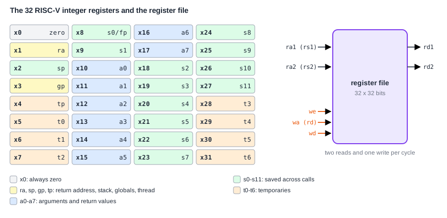
To the hardware, x1 to x31 are identical. But separate pieces of software have to cooperate: a function compiled today must be able to call a library compiled last year by a different compiler. They can only do that if they agree on rules such as "the first argument is passed in x10" and "the return value comes back in x10". That set of rules is the application binary interface (ABI), and the part about function calls is the calling convention.
The ABI gives each register a name that says its role, shown in the picture above: a0-a7 carry function arguments and return values, ra holds the return address of a call, sp points to the top of the stack, t0-t6 are temporaries and s0-s11 are saved registers. Disassemblers print these names, which is why compiled code shows add a0,a0,a5 rather than add x10,x10,x15.
The most important rule is who must preserve which registers across a call. A called function may overwrite the temporaries and argument registers freely; these are caller-saved, meaning that a caller who still needs a value in them must save it first. The saved registers s0-s11 are callee-saved: a called function that wants to use one must store its old value and restore it before returning. Here is the start of a compiled main function that calls a printing routine and needs several values afterwards:
main:
    addi sp,sp,-32          # make room for 8 words on the stack
    sw   s1,20(sp)          # main will use s1, s2, s0 and s3, so it
    sw   s2,16(sp)          # first saves their old values (callee-saved)
    sw   ra,28(sp)          # and its own return address, because the
    sw   s0,24(sp)          # call below will overwrite ra
    sw   s3,12(sp)
    ...
    jalr -156(ra)           # call uart_puts
The function saves exactly the registers the convention says it must. How a Program Runs follows calls and the stack in detail.
Quick Check
Q: A function keeps a running total in t0 and then calls another function. Why might the total be wrong when the call returns?
Show Answer
t0 is caller-saved: the called function is allowed to overwrite it without restoring it. To keep the total across the call, the caller must either save t0 on the stack before the call or keep the total in a saved register such as s1 from the start.
Who Decides What Lives in Registers: The Compiler
Programs are usually written in a language such as C, but the processor only runs machine instructions. A compiler is the program that translates one into the other. For each C function it chooses the instructions, and it decides where every variable lives: in a register, or in memory on the stack. That decision is called register allocation, and it has a large effect on speed.
Compilers let the user choose how hard they should work, through optimization levels given on the command line. With GCC, -O0 means "no optimization": the compiler translates each line of C as directly as possible, keeps every variable in memory, and reloads it every time it is used. That code is slow but easy to follow in a debugger, because each variable always has an up-to-date copy in memory. -O2 means "optimize": the compiler keeps values in registers, removes repeated work and rearranges code, as long as the result of the program stays the same. Production software is normally compiled with optimization; Compiler Optimization Levels compares the settings.
The difference is easy to see. This is a loop that adds up an array, compiled both ways for RV32I. First with -O2, where the pointer, the end address and the total all stay in registers:
44:  lw   a5,0(a4)          # load the next array element
48:  addi a4,a4,4           # move the pointer to the next element
4c:  add  a0,a0,a5          # total = total + element
50:  bne  a4,a2,44          # repeat until the pointer reaches the end
And the same loop with -O0, where the loop counter i lives at stack offset -28 and the total at offset -24, and both are reloaded and stored back on every pass:
7c:  lui  a5,0x0
80:  addi a4,a5,204         # address of the array
84:  lw   a5,-28(s0)        # load i from the stack
88:  slli a5,a5,0x2         # i * 4: byte offset of a[i]
8c:  add  a5,a4,a5          # address of a[i]
90:  lw   a5,0(a5)          # load a[i]
94:  lw   a4,-24(s0)        # load total from the stack
98:  add  a5,a4,a5          # total + a[i]
9c:  sw   a5,-24(s0)        # store total back to the stack
a0:  lw   a5,-28(s0)        # load i again
a4:  addi a5,a5,1           # i + 1
a8:  sw   a5,-28(s0)        # store i back
ac:  lw   a4,-28(s0)        # load i once more for the loop test
b0:  li   a5,1023
b4:  bgeu a5,a4,7c          # repeat while i <= 1023
The optimized loop needs 4 instructions and 1 load per element; the unoptimized one needs 15 instructions and 5 loads. When a function has more live values than there are free registers, even an optimizing compiler must keep some of them in memory; storing a value from a register to the stack to free the register is called spilling. What a Compiler Does covers compilers and their optimizations in depth.
Measuring the Difference
In one test, both versions of this program ran on a simple five-stage processor. They compute the same result, but the unoptimized build executes about 4 times as many instructions, makes 9 times as many loads and 4 times as many stores, and takes 3.5 times as long.
The optimized build loads each array element once and stores it once while filling the array. All the extra loads and stores in the unoptimized build are traffic between registers and the stack, which the optimized code avoids.
There is a further cost. A load-use stall happens when an instruction needs a value that the previous instruction is still loading from memory; the processor must wait one cycle for the data to arrive. The unoptimized code constantly loads a variable and uses it immediately, so about one cycle in seven was lost this way. The optimized loop lost none. A processor with a faster memory path, or one that runs other work during the wait, would lose less, so the exact ratio changes from one design to another; the direction does not.
Where Does This Matter?
Software teams ship optimized builds and debug with unoptimized ones, and performance measurements are only meaningful on the optimized build. Architects study how many registers compilers actually need when they design a new instruction set, because running out of registers forces spilling and adds memory traffic.
Inside the Register File
The register file is the circuit that holds the 32 architectural registers. A typical instruction such as add a0, a0, a5 reads two registers and writes one, so the register file is built to do exactly that in every cycle: it has two read ports and one write port. A port is an independent way in or out: each read port has its own register-number input and its own data output, so both reads happen at the same time.
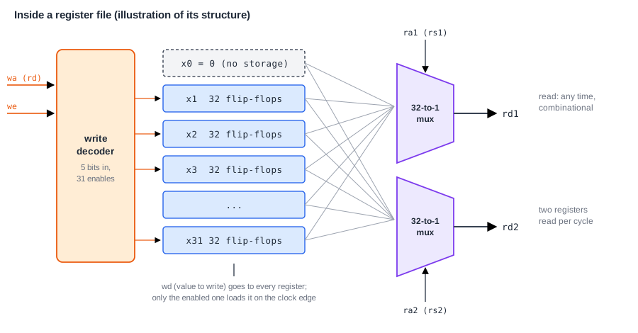
Each read port is a multiplexer, a selector circuit that picks one of its inputs. A 32-to-1 multiplexer of 32-bit values takes all 32 registers as inputs and uses the 5-bit register number to pass the chosen one to its output. Reading is combinational: the output follows the register number within the cycle, with no clock edge needed. (The multiplexer article shows how one is built from gates.)
The write port uses a decoder: it turns the 5-bit destination register number into 31 separate enable signals, one per register x1 to x31, of which exactly one is active. The value to write goes to every register, but only the enabled one loads it, on the next clock edge, and only if the instruction actually writes a register (the write enable is on). x0 has no flip-flops at all: its read input is simply tied to zero.
In a small processor the register file is the largest single piece of storage in the core. It needs 31 x 32 = 992 flip-flops, and in one small five-stage core that came to almost three quarters of all the flip-flops in the design.
Reading a Register While It Is Being Written
One more detail matters in a processor that works on several instructions at once. An instruction writes its result into the register file in its last step, while a younger instruction may be reading registers in an earlier step of the same cycle. If both name the same register, the read would see the old value, because the write only takes effect at the end of the cycle. The register file therefore checks for this case and passes the value being written straight to the read port:
always @(*) begin
    if (ra1 == 5'd0)
        rd1 = 32'd0;              // x0 always reads as zero
    else if (we && wa == ra1)
        rd1 = wd;                 // being written this cycle: use the new value
    else
        rd1 = regs[ra1];          // otherwise the stored value
end
This is called write-through or bypassing. The second read port has the same logic. Without it, the processor would have to wait an extra cycle every time an instruction used a result written just before. The Instruction Cycle explains the steps an instruction goes through, and the pipelining chapter shows where this case arises.
Common Mistakes
Mistake #1: Building x0 as a normal register
If x0 can be written, every instruction that relies on it reading zero breaks: li, mv, nop and every comparison with zero. x0 must always read as zero, whatever is written to it.
Mistake #2: Ignoring the calling convention in hand-written assembly
Assembly code that changes a saved register without restoring it works until it is called from compiled code, which then fails somewhere else, much later. Follow the convention whenever code calls, or is called by, other code.
Mistake #3: Measuring performance with unoptimized code
An -O0 build spends most of its time moving variables between registers and memory, as the measurement above shows. Benchmarks and design studies must use the optimization level the real software ships with.
Practice Exercise
Challenge: Count the Loads From the Listing
The unoptimized array program has two loops, each running 1,024 times. The second loop is listed above. The first loop, which fills the array, executes the loads lw a4,-20(s0) at 0x2c, lw a5,-20(s0) at 0x48 and 0x58, and the loop test lw a4,-20(s0) at 0x64. Both loops start by jumping to their loop test, and after the second loop the function executes two more loads: lw a5,-24(s0) to fetch the total and lw s0,28(sp) to restore s0. Predict the total number of loads.
Hint
Because each loop jumps to its test first, the test runs once more than the loop body: 1,025 times. Count the loads in each loop's body and in its test separately.
Solution
First loop: 3 loads in the body x 1,024 = 3,072, plus the test load x 1,025 = 1,025, giving 4,097. Second loop: 4 loads in the body (at 0x84, 0x90, 0x94 and 0xa0) x 1,024 = 4,096, plus the test load at 0xac x 1,025 = 1,025, giving 5,121. After the loops: 2. Total: 4,097 + 5,121 + 2 = 9,220, and a real run gives exactly this count. Almost all of these loads exist only because -O0 keeps the variables in memory; the optimized build needs one load per element, 9 times fewer.
Summary
- A register is a group of flip-flops inside the core; it is fast because it is wired directly to the ALU and needs no memory access.
- RISC-V has 32 registers because 5-bit fields name 32, and more would cost instruction bits, area and speed; x0 always reads as zero.
- The ABI names registers by role and the calling convention decides which ones survive a call (callee-saved s0-s11) and which do not.
- The compiler decides which values live in registers; in one array loop,
-O0made 9 times as many loads as-O2and took 3.5 times as long. - The register file has two read ports (multiplexers) and one write port (a decoder and enables), with write-through so a read never sees a stale value.
