
A processor does one thing, over and over: it reads an instruction from memory, works out what the instruction asks for, does it, and moves on to the next one. This repeating sequence is the instruction cycle, and every program, from a boot loader to an operating system, is nothing more than the processor running it billions of times. This article explains the program counter, the five steps of the instruction cycle, how the next instruction is chosen, and how a real processor overlaps the steps, following the first instructions of a small RISC-V program through each one.
14 min read | Beginner
What You'll Learn
- Explain the role of the program counter and where execution starts
- Describe the five steps of the instruction cycle for different kinds of instructions
- Work out the next program counter for sequential code, branches and jumps
- Explain how pipelining overlaps the steps and read a pipeline diagram
The Program Counter
A program in memory is a list of instructions, each 4 bytes long in RV32I, stored one after another. The processor keeps track of where it is in that list with a special register, the program counter or PC. The PC holds the address of the instruction being run. It is not one of the 32 general-purpose registers: no ordinary instruction names it, and it changes by itself as instructions run.
When the processor is switched on or reset, the PC is set to a fixed reset address, where the first instruction must be. In the example below the reset address is 0, so the program is linked to start at address 0. From then on the processor needs no outside help: it fetches the instruction the PC points to, executes it, updates the PC, and repeats until it is switched off.
The Five Steps
Running one instruction breaks down into five steps. Their names come from the classic RISC processor designs and are used throughout the industry, usually shortened to two or three letters:
| Step | Name | What the hardware does |
|---|---|---|
| IF | Instruction fetch | send the PC to the instruction memory and read the 32-bit instruction stored there |
| ID | Instruction decode | split the instruction into its fields, find out what operation it is, and read its source registers |
| EX | Execute | do the arithmetic: the ALU (arithmetic logic unit) computes a result, a memory address or a branch decision |
| MEM | Memory access | for loads and stores, read or write the data memory; other instructions pass through |
| WB | Write back | write the result into the destination register |
Take lw a5, 0(a4), which loads the word at the address in register a4 into register a5. In IF the processor reads its encoding, 0x00072783, from memory. In ID it finds the opcode for a load, the size (a word), the source register a4, the destination a5 and the offset 0, and reads the value of a4. In EX the ALU adds a4 + 0 to form the address. In MEM the data memory returns the word at that address. In WB that word is written into a5.
Not Every Instruction Uses Every Step
Different kinds of instructions need different steps. An add computes its result in EX and has nothing to do in MEM. A store writes memory in MEM but has no destination register. A branch only decides, in EX, whether to change the PC:
| Instruction | IF | ID | EX | MEM | WB |
|---|---|---|---|---|---|
| add a0, a1, a2 | fetch | read a1, a2 | a1 + a2 | - | write a0 |
| lw a5, 0(a4) | fetch | read a4 | address a4 + 0 | read memory | write a5 |
| sw a5, 0(a1) | fetch | read a1, a5 | address a1 + 0 | write memory | - |
| bnez a5, 3c | fetch | read a5 | compare a5 with 0, compute target | - | - |
| jal ra, target | fetch | - | compute target and PC + 4 | - | write ra |
Processors still give every instruction the same five slots, with some of them empty. Keeping one fixed sequence makes the hardware regular: the same circuits do the same step for every instruction, and the control logic only has to switch parts on or off.
Quick Check
Q: Which steps does sb a5, 2(a4) (store byte) do real work in, and what does it do in each?
Show Answer
IF fetches it; ID decodes it and reads a4 and a5; EX adds a4 + 2 to form the address; MEM writes the low byte of a5 at that address. WB has nothing to do, because a store writes no register.
Choosing the Next Instruction
While an instruction runs, the processor also works out the address of the next one, the next PC. There are three cases:
- Sequential: most instructions are followed by the one right after them in memory, at PC + 4.
- Branch: a conditional branch such as
beqorbnezcompares two registers. If the condition is true the branch is taken and the next PC is the PC plus an offset encoded in the instruction; otherwise it is not taken and execution continues at PC + 4. Loops and if statements are built from branches. - Jump:
jal(jump and link) always jumps to PC + offset;jalr(jump and link register) jumps to a register plus an offset. Both save PC + 4, the address of the instruction after the jump, into a destination register. That saved address is the return address, and it is how functions are called and how they return.
Following a Real Program
A small program without an operating system usually starts with a few instructions called _start, which prepare the processor and then call the program's main function. Here they are for a program that prints a greeting, as the disassembler shows them:
00000000 <_start>: 0: 00010137 lui sp,0x10 4: 00000097 auipc ra,0x0 8: 014080e7 jalr ra,20(ra) # call main at 0x18 c: f00002b7 lui t0,0xf0000 10: 00a2a023 sw a0,0(t0) # write main's result to EXIT 14: 0000006f j 14 # stay here 00000018: 18: f00005b7 lui a1,0xf0000 ... 68: 00008067 ret # return to the address in ra
Follow the PC through them:
| PC | Instruction | What it does | Next PC |
|---|---|---|---|
| 0x00 | lui sp, 0x10 | sp = 0x10 shifted left 12 bits = 0x0001_0000, the top of the 64 KB memory, where the stack starts | 0x04 (sequential) |
| 0x04 | auipc ra, 0x0 | ra = PC + 0 = 0x04 ("add upper immediate to PC") | 0x08 (sequential) |
| 0x08 | jalr ra, 20(ra) | jump to ra + 20 = 0x04 + 0x14 = 0x18, and save the return address 0x0C in ra | 0x18 (jump) |
| 0x18 to 0x68 | main | prints the message, leaves its result in a0 | - |
| 0x68 | ret | short for jalr zero, 0(ra): jump to the address in ra, save nothing | 0x0C (jump) |
| 0x0C, 0x10 | lui t0 / sw a0 | store a0 to address 0xF000_0000, the EXIT register, which ends the run | 0x14 |
| 0x14 | j 14 | jump to itself, an endless loop in case nothing stops the processor | 0x14 (jump) |
The call and return show why jumps save PC + 4. jalr at 0x08 stored 0x0C in ra, so when main finished, ret could jump back to the instruction right after the call. The processor itself knows nothing about functions; it only follows the PC, and the program arranges the jumps. The Calling Convention and ABI explains the rules software follows for calls.
The final j 14 shows something else: a processor never "finishes". There is no instruction that stops it in RV32I. A program ends by telling the outside world it is done, here with a store to a device register, and then waits in a loop.
One Instruction at a Time
The simplest way to build the instruction cycle is to finish one instruction completely before starting the next. There are two classic ways to do that:
- A single-cycle processor does all five steps in one long clock cycle. It needs no registers between the steps, but the clock period must cover fetch, decode, execute, memory and write back one after the other, so the clock is slow.
- A multi-cycle processor does one step per clock cycle and needs up to five cycles per instruction. Its clock can be fast, because each cycle covers only one step, but most of the hardware sits idle most of the time: while the ALU works on one instruction, the instruction memory waits.
The greeting program executes about 200 instructions. A multi-cycle processor that took five cycles for each would need about 200 x 5 = 1,000 cycles. Single-Cycle and Multi-Cycle Processors compares the two designs in detail.
Overlapping the Steps: Pipelining
The steps use different hardware, so nothing prevents the processor from working on several instructions at once, each in a different step. While one instruction executes, the next can be decoded and the one after it fetched. This is pipelining. A five-stage pipeline starts a new instruction every cycle, so up to five instructions are in flight at once. In one test, a five-stage pipeline ran the greeting program in less than a third of the cycles the multi-cycle design needs.
A pipeline diagram shows this, with time running left to right in cycles and one row per instruction. The diagram below shows the first cycles of the greeting program:
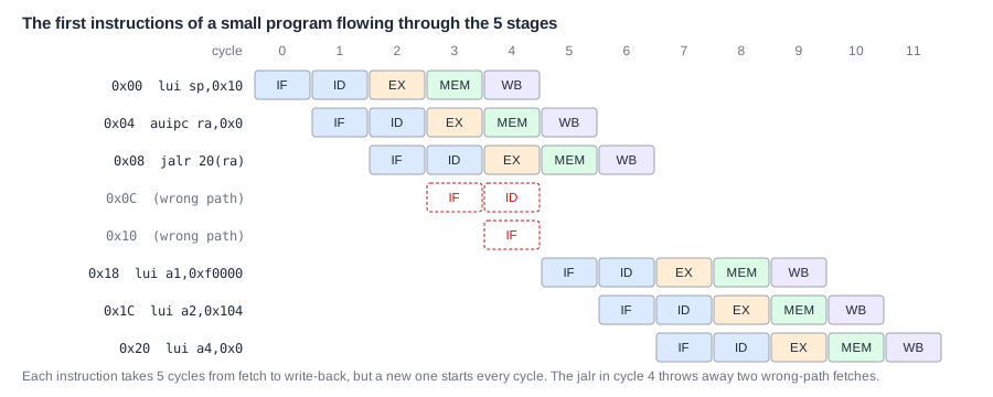
The first instruction, lui sp, is fetched in cycle 0, decoded in cycle 1, executes in cycle 2, passes MEM in cycle 3 and writes sp in cycle 4. The next two instructions follow, each one cycle behind. Then the jump has an effect. When jalr executes in cycle 4, the processor has already fetched the two instructions after it, at 0x0C and 0x10, because it did not yet know a jump was coming. Those two are discarded, which is called a flush, and fetching restarts at 0x18. The first instruction of main therefore executes in cycle 7 instead of cycle 5: the jump cost two cycles.
Latency and Throughput
Pipelining does not make a single instruction faster. Each instruction still takes five cycles from fetch to write back; that time is its latency. What improves is the throughput, the number of instructions finished per cycle, which is up to one in a five-stage pipeline instead of one every five cycles. Programs consist of many instructions, so throughput is what decides their run time.
Pipelining has costs too. Besides flushes after taken branches and jumps, an instruction sometimes needs a result that an earlier instruction has not produced yet, and must wait. That is why the test above took about 1.4 cycles per instruction rather than exactly 1. Better designs lower that figure, but none reaches a perfect 1 on every program. The Pipelining chapter explains these hazards and how processors reduce them.
Where Is This Used?
Every processor in use today pipelines the instruction cycle. Small microcontroller cores use two to five stages; high-performance cores split the same steps into fifteen or more stages so that each stage is short and the clock can run fast, and they fetch and execute several instructions per cycle.
Quick Check
Q: In the diagram above, in which cycle does the third instruction, jalr, write its result into ra? How many cycles would a multi-cycle design that needs five cycles per instruction take to finish the same three instructions?
Show Answer
jalr executes in cycle 4, so it writes back two cycles later, in cycle 6: all three instructions finish within 7 cycles (0 to 6). The multi-cycle design would take 3 x 5 = 15 cycles.
What the Hardware Keeps Between Steps
For the steps to overlap, each instruction must carry its information with it as it moves along. Between every two steps, a pipelined processor has a set of registers, the pipeline registers, which on each clock edge take over everything the next step needs. They are usually named after the stage they feed. The registers in front of decode hold the instruction and its PC. The ones in front of execute hold the PC, the two register values read in decode, the immediate, the register numbers and the control signals that say what to do. The ones in front of the memory step hold the ALU result and the value to store, and the ones in front of write back hold the final value and the number of the register to write.
Each set also carries a valid bit. When the processor discards fetched instructions after a jump, it does not erase anything; it simply clears their valid bits, and the later steps ignore them. That is how the two instructions behind jalr in the trace disappear without changing any register or memory.
Common Mistakes
Mistake #1: Thinking the PC is a normal register
RV32I instructions cannot name the PC as a source or destination. It changes only through the instruction cycle itself: by 4 after most instructions, or to a target after a taken branch or jump. auipc is the way to read it.
Mistake #2: Confusing latency with throughput
In a five-stage pipeline one instruction takes five cycles from fetch to write back, yet up to one instruction finishes every cycle. Performance depends on how many finish per cycle, not on how long one takes.
Mistake #3: Forgetting that fetch runs ahead
By the time a branch or jump is decided, a pipelined processor has already fetched the instructions after it. If the branch is taken, they are discarded, which costs cycles even though they never ran.
Practice Exercise
Challenge: Follow the PC
Suppose the _start code above were linked so that main starts at 0x40 instead of 0x18, and the compiler changed the jalr offset to match. (a) What offset must jalr ra, offset(ra) use? (b) Which value does ra hold after the jalr, and where does ret jump to? (c) If main executes 200 instructions, how many cycles would a five-cycles-per-instruction design need for the whole program, counting the six _start instructions that run (including the final j 14 once)?
Hint
When jalr runs, ra still holds the value auipc put there: the address of the auipc itself.
Solution
(a) ra = 0x04, so the offset must be 0x40 - 0x04 = 0x3C = 60. (b) ra = 0x0C, the address after the jalr, whatever the target; ret jumps back to 0x0C, where the result is written to EXIT. (c) 200 + 6 = 206 instructions x 5 cycles = 1,030 cycles.
Summary
- The PC holds the address of the current instruction; it starts at a fixed reset address.
- Every instruction goes through fetch, decode, execute, memory access and write back, with unused steps left empty.
- The next PC is PC + 4, a branch target if a branch is taken, or a jump target; jumps save PC + 4 as the return address.
- A pipeline overlaps the steps: one test took less than a third of the cycles of a five-cycle-per-instruction design.
- Latency is the time for one instruction; throughput, instructions per cycle, is what sets run time.
