
Every instruction a RISC-V processor executes is a 32-bit number. The instruction set defines exactly how those 32 bits are divided: which bits name the operation, which name the registers, and where any constant goes. RV32I uses only six arrangements, called formats, and they are designed so that the hardware can decode them quickly. This article explains the six formats field by field, decodes real instructions from a compiled RISC-V program bit by bit, and shows why the constants in some formats look scrambled and why that makes the processor simpler.
13 min read | Beginner
What You'll Learn
- Name the six RV32I instruction formats and the fields of each
- Decode a 32-bit instruction word into its operation, registers and immediate
- Encode a simple instruction by hand from its assembly form
- Explain why RISC-V places fields where it does, including the scattered immediates
Instructions Are Numbers
In memory, a program is a sequence of 32-bit words. The listing of a small RISC-V program shows each instruction as its address, its 32-bit value in hexadecimal and its meaning in assembly language:
  18:  f00005b7   lui   a1,0xf0000
  24:  06c70713   addi  a4,a4,108
  3c:  00f5a023   sw    a5,0(a1)
  40:  00074783   lbu   a5,0(a4)
  64:  fc079ce3   bnez  a5,3c
The assembly text exists only for people. The processor sees just the numbers. The program that turns assembly text into these numbers is the assembler, and the tool that turns them back into text, as in this listing, is the disassembler. Both follow the encoding rules of the ISA, which this article explains.
An encoding has to answer three questions for each instruction: what operation it is, which registers it uses, and what constant, if any, it carries. RISC-V answers them with fields, groups of bits at fixed positions.
The Fields
Six kinds of field appear in RV32I instructions:
| Field | Bits | Meaning |
|---|---|---|
| opcode | 7 bits, always 6 to 0 | the major kind of instruction: register arithmetic, immediate arithmetic, load, store, branch, jump, ... |
| rd | 5 bits, 11 to 7 | the destination register, 0 to 31 |
| funct3 | 3 bits, 14 to 12 | selects among related operations, such as add/xor/or, or the size of a load |
| rs1 | 5 bits, 19 to 15 | the first source register |
| rs2 | 5 bits, 24 to 20 | the second source register |
| funct7 | 7 bits, 31 to 25 | a further operation selector; bit 30 distinguishes add from sub and srl from sra |
A register field is 5 bits because 25 = 32, exactly the number of registers. Everything that is not a register field or an operation field holds part of an immediate, the constant built into the instruction.
The Six Formats
Different kinds of instruction need different fields. An addition of two registers needs three register numbers and no constant; an addition of a register and a constant needs two registers and a constant; a store needs two source registers and an offset but no destination. RV32I covers all its instructions with six formats:
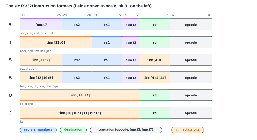
- R-type (register): two source registers and a destination, for operations like
add,sub,and,sll. - I-type (immediate): one source register, a destination and a 12-bit immediate, for
addiand the other immediate arithmetic, for loads (the immediate is the address offset) and forjalr. - S-type (store): two source registers (the address base and the value to store) and a 12-bit offset, split into two pieces because there is no rd.
- B-type (branch): two source registers to compare and a 13-bit branch offset, again split.
- U-type (upper immediate): a destination and a 20-bit immediate that fills the upper 20 bits of a 32-bit value, for
luiandauipc. - J-type (jump): a destination and a 21-bit jump offset, for
jal.
The fields that exist in several formats are always in the same place. The opcode is always bits 6 to 0, rd always 11 to 7, rs1 always 19 to 15, rs2 always 24 to 20. This regularity is the key design idea, and the reason is explained after the examples.
Decoding Real Instructions
Decoding means splitting the 32 bits into fields and reading each one. Writing the word in binary and splitting it at the field boundaries is all it takes.
R-type: add a0, a0, a5
| Field | funct7 | rs2 | rs1 | funct3 | rd | opcode |
|---|---|---|---|---|---|---|
| Bits of 0x00F50533 | 0000000 | 01111 | 01010 | 000 | 01010 | 0110011 |
| Meaning | add (not sub) | 15 = a5 | 10 = a0 | add/sub group | 10 = a0 | register-register arithmetic |
Register numbers become names through the ABI table in Registers and the Register File: x10 is a0, x15 is a5. The same program contains sub a1, a1, a2 as 0x40C585B3, whose funct7 is 0100000: bit 30 is the only difference between an add and a sub.
I-type: addi a5, a5, -97
| Field | imm[11:0] | rs1 | funct3 | rd | opcode |
|---|---|---|---|---|---|
| Bits of 0xF9F78793 | 111110011111 | 01111 | 000 | 01111 | 0010011 |
| Meaning | 0xF9F = -97 (bit 11 is 1) | 15 = a5 | addi | 15 = a5 | immediate arithmetic |
The immediate is a 12-bit two's complement number, so it ranges from -2,048 to +2,047. The hardware sign-extends it to 32 bits by copying bit 11, the instruction's bit 31, into all the upper bits. In a compiled test for vowels this instruction subtracts the code of 'a' (97) from a character. Numbers in Hardware explains two's complement and sign extension.
I-type load: lbu a5, 0(a4)
| Field | imm[11:0] | rs1 | funct3 | rd | opcode |
|---|---|---|---|---|---|
| Bits of 0x00074783 | 000000000000 | 01110 | 100 | 01111 | 0000011 |
| Meaning | offset 0 | 14 = a4 (base) | lbu | 15 = a5 | load |
Loads use the I format: the immediate is the offset added to rs1. funct3 picks the size and the extension: 000 lb, 001 lh, 010 lw, 100 lbu, 101 lhu.
S-type: sw a5, 0(a1)
| Field | imm[11:5] | rs2 | rs1 | funct3 | imm[4:0] | opcode |
|---|---|---|---|---|---|---|
| Bits of 0x00F5A023 | 0000000 | 01111 | 01011 | 010 | 00000 | 0100011 |
| Meaning | offset 0 | 15 = a5 (value) | 11 = a1 (base) | sw | offset 0 | store |
A store has no destination register, so the bits where rd would be carry the low five bits of the offset instead. The offset is still 12 bits, split into two pieces so that rs1 and rs2 stay where they are in every other format.
Quick Check
Q: Decode 0x06C70713. Which format and instruction is it, and what are its registers and immediate?
Show Answer
Binary 000001101100 01110 000 01110 0010011. Opcode 0010011 with funct3 000 is addi (I-type); rs1 = 14 = a4, rd = 14 = a4, imm = 0x06C = 108. It is addi a4, a4, 108, which builds the address 0x6C of a message in memory.
The Scattered Immediates
The branch and jump formats are the unusual ones. Their immediates are not stored as one continuous block but scattered over the instruction in an order that looks almost random. The branch at address 0x64 of the same program shows how to read one:
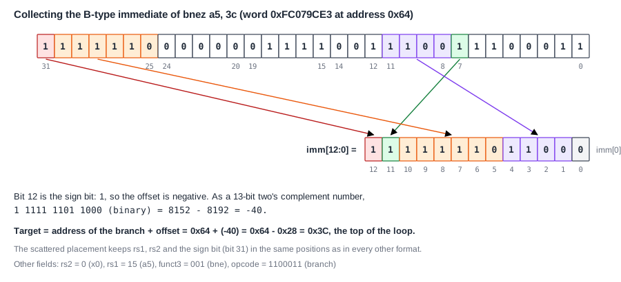
The B-type immediate is 13 bits, imm[12:0], but bit 0 is not stored at all: branch targets are always at even addresses, so imm[0] is always 0 and the instruction does not waste a bit on it. The other twelve bits come from four places: imm[12] from instruction bit 31, imm[10:5] from bits 30 to 25, imm[4:1] from bits 11 to 8, and imm[11] from bit 7. For 0xFC079CE3 that gives 1 1111 1101 1000 in binary, which is -40 as a 13-bit signed number. The branch target is the branch's own address plus the offset: 0x64 - 40 = 0x3C, the top of the loop that prints each character.
The rest of the word is ordinary: opcode 1100011 is a branch, funct3 001 is bne, rs1 is a5 and rs2 is x0. The disassembler shows bnez a5, 3c, "branch if a5 is not zero", which is a more readable name for bne a5, x0, 3c.
The J-type immediate of jal is scattered in the same spirit, over 20 bits: imm[20], imm[10:1], imm[11] and imm[19:12]. With imm[0] again implicit, it reaches targets up to about 1 MB away in either direction. A branch's 13-bit offset reaches about 4 KB in either direction, enough for almost every loop and if statement.
Why the Formats Look Like This
The scrambled bit orders are not an accident. They follow from two goals: make decoding fast, and make the decoder small.
Register fields never move. Because rs1 and rs2 are in the same bits in every format that has them, the processor can start reading the register file in the first moment of decode, before it has even worked out what kind of instruction it has. If the fields moved, it would first have to decode the opcode, then select where to find the register numbers, and only then read the registers, a longer path in a critical part of the pipeline.
The sign bit never moves. In every format with an immediate, the immediate's sign is instruction bit 31. Sign extension, copying the sign into all upper bits, therefore uses the same wire for every format and can start right away.
Immediate bits overlap as much as possible. Within the immediate, the formats are arranged so that each bit of the 32-bit immediate comes from the same instruction bit in as many formats as possible. imm[10:5], for example, comes from bits 30 to 25 in the I, S, B and J formats. The circuit that builds the immediate then needs only a few small multiplexers instead of one large one per bit. The scattering of the B and J immediates is the price of this overlap: they are shuffled so that their bits line up with the I and S immediates rather than with each other.
A simple decoder shows the result. It builds all five immediates, I, S, B, U and J, from the instruction with fixed wiring, each one a single line of RTL (the hardware description code), and then selects one of them based on the opcode. No bit of the instruction needs any logic before it reaches its place in an immediate.
Where Does This Matter?
Decoders sit in the front of every processor pipeline, and in wide cores that decode several instructions per cycle, their speed and size multiply. Verification teams also depend on encodings: instruction generators produce millions of random but valid instruction words, and checkers compare the processor against a reference model that decodes the same bits. A single field placed wrong in the decoder breaks every instruction that uses it.
Encoding by Hand
Encoding is decoding in reverse: look up the opcode and function fields of the instruction, write each field in binary, and concatenate them in format order. For sub a0, a1, a2:
| Field | funct7 | rs2 | rs1 | funct3 | rd | opcode |
|---|---|---|---|---|---|---|
| Bits | 0100000 | 01100 | 01011 | 000 | 01010 | 0110011 |
| Meaning | sub | 12 = a2 | 11 = a1 | sub | 10 = a0 | register arithmetic |
binary: 0100 0000 1100 0101 1000 0101 0011 0011
hex:    0x40C58533
Grouping the 32 bits in fours from the left gives the hexadecimal digits. In practice the assembler does this, but encoding a few instructions by hand is the best way to remember the formats, and engineers do it when they read raw memory dumps or write test patterns for a processor.
Quick Check
Q: Which format does jalr ra, 20(ra) use, and why not the J format?
Show Answer
I-type. jalr jumps to a register plus a 12-bit offset, so it needs rs1, rd and a 12-bit immediate, exactly the I fields. The J format has no rs1; it is for jal, which jumps relative to the PC with a larger 20-bit offset.
Common Mistakes
Mistake #1: Forgetting the implicit zero of branch offsets
The B and J immediates do not store bit 0. Decoding the stored bits as if they started at bit 0 gives an offset half the real size, and the branch goes to the wrong address.
Mistake #2: Treating the immediate as unsigned
In every RV32I format, instruction bit 31 is the sign of the immediate, and 12-bit immediates are sign-extended to 32 bits. 0xF9F in an addi is -97, not 3,999.
Mistake #3: Splitting the binary at the wrong boundaries
The fields are 7, 5, 5, 3, 5 and 7 bits wide in an R-type instruction, not groups of four. Write the 32 bits out in full, then split at bits 25, 20, 15, 12 and 7.
Practice Exercise
Challenge: Decode a Loop
A loop in a compiled program is these four words, at addresses 0x44 to 0x50: 0x00072783, 0x00470713, 0x00F50533, 0xFEC71AE3. Decode each one: format, instruction, registers and immediate. Then say where the branch jumps to and what the loop computes.
Hint
Look at the opcode first (bits 6 to 0): 0000011 is a load, 0010011 immediate arithmetic, 0110011 register arithmetic, 1100011 a branch. For the branch, assemble the B immediate from bits 31, 7, 30 to 25 and 11 to 8.
Solution
0x00072783: I-type load, funct3 010 = lw a5, 0(a4). 0x00470713: addi a4, a4, 4. 0x00F50533: R-type add a0, a0, a5. 0xFEC71AE3: B-type, funct3 001 = bne, rs1 = 14 (a4), rs2 = 12 (a2); the immediate bits give 1 1111 1111 0100 = -12, so the target is 0x50 - 12 = 0x44. The loop is bne a4, a2, 44 back to the load: it reads a word, moves the pointer on by 4, adds the word to a0, and repeats until the pointer a4 reaches the end address in a2. It sums the array.
Summary
- Every RV32I instruction is a 32-bit word made of fields: opcode, rd, funct3, rs1, rs2, funct7 and immediate bits.
- Six formats, R, I, S, B, U and J, cover all instructions; shared fields are always in the same bit positions.
- Immediates are sign-extended from bit 31; B and J immediates omit bit 0 and are scattered to line up with the others.
- The branch 0xFC079CE3 at 0x64 carries the offset -40 and jumps to 0x3C.
- Fixed field positions let the processor read registers and build immediates before it has finished decoding.
