
Assembling, linking and loading are the three steps that turn a compiler's output into a program sitting in a processor's memory, ready to run. The compiler only translates one source file at a time, and it does not know where its code will end up or where the functions it calls live; the assembler, the linker and the loader settle those questions. Problems in these steps are some of the most common and most confusing in embedded and chip work: an "undefined reference", a program that runs in simulation but not on the board, a variable that is not zero at start-up. This article follows one small linked-list program, list.c, from its object file, with its symbols and relocations, through the linker and its linker script, to the 146 words that end up in memory.
21 min read | Beginner
What You'll Learn
- Explain what an assembler produces and what an object file contains: sections, symbols and relocations
- Describe the three jobs of a linker and read a linker script and a link map
- Explain why a RISC-V call is an auipc and jalr pair, and what linker relaxation changes
- Trace how an executable becomes the words a processor finds in memory at reset
Four Steps From Source to Memory
Building a program takes four tools, run one after another. The compiler translates C into assembly language, the text form of machine instructions (the What a Compiler Does article opens it up). The assembler translates assembly language into machine code and writes an object file. The linker joins all the object files of a program, plus any library code they need, into one executable. Finally a loader copies the executable into memory and starts it.
A programmer rarely runs these tools one by one. The command riscv64-unknown-elf-gcc is a driver: given C files, assembly files and options, it runs the compiler, the assembler (as) and the linker (ld) in turn and deletes the files in between. A small embedded program is usually built by a single such command, which takes the start-up code crt0.S, the program, here list.c, and the support library libgcc. To look at the steps, this article runs them separately on those two source files and keeps every file in between.
The Assembler
Assembly language is one line per instruction, using names instead of numbers. Here is the start of the assembly file GCC writes for a small program that adds up an array:
	.attribute stack_align, 16
	.text
	.section	.text.startup,"ax",@progbits
	.align	2
	.globl	main
	.type	main, @function
main:
	lui	a5,%hi(a)
	addi	a4,a5,%lo(a)
	...
	.bss
	.align	2
	.type	a, @object
	.size	a, 4096
a:
	.zero	4096
Lines that start with a dot are directives: instructions to the assembler itself, not to the processor. .section says which part of the output the following lines belong to, .globl main makes the name main visible to other files, .align 2 moves to an address that is a multiple of 22 = 4 bytes, and .zero 4096 reserves 4,096 bytes of zeros for the array a. Names followed by a colon, such as main:, are labels: they give the current address a name.
For each instruction line the assembler looks up the opcode, puts the register numbers and the constant into the right bit fields and writes the 32-bit word. It also expands pseudo-instructions such as li and call into one or two real instructions. What the assembler cannot do is fill in an address it does not know yet. In lui a5,%hi(a), %hi(a) means "the upper 20 bits of the address of a", and that address will only be decided when the linker places the array. The assembler writes zero into the field for now and leaves a note for the linker. Those notes, and the names they refer to, are what make an object file more than a block of machine code.
Inside an Object File
Object files and executables on most systems use the ELF format (Executable and Linkable Format). An ELF file is a header followed by a set of sections, each a named block of bytes with a purpose. readelf -S lists them. These are the important sections of list.o, the object file of the linked-list program:
  [Nr] Name              Type            Addr     Off    Size   ES Flg Lk Inf Al
  [ 1] .text             PROGBITS        00000000 000034 000000 00  AX  0   0  4
  [ 2] .data             PROGBITS        00000000 000034 000000 00  WA  0   0  1
  [ 3] .bss              NOBITS          00000000 000034 001800 00  WA  0   0  4
  [ 4] .text.startup     PROGBITS        00000000 000034 00017c 00  AX  0   0  4
  [ 5] .rela.text.startup RELA            00000000 000354 0000c0 0c   I  8   4  4
  [ 8] .symtab           SYMTAB          00000000 0001f0 000120 10      9  16  4
The machine code of main is in .text.startup: 0x17c = 380 bytes. GCC puts main in a section of that name instead of the usual .text because it knows main runs only once, and some systems place such code apart from code that runs often. .bss holds the two arrays, order and nodes, 0x1800 = 6,144 bytes, but its type is NOBITS: the file stores only the size, not 6,144 zero bytes. .data, for global variables with initial values, is empty because this program has none. Every address (the Addr column) is 0: an object file has not been placed in memory yet, so all positions in it are offsets from the start of each section.
The flags say how each section will be used: A (allocated: it occupies memory when the program runs), X (executable) and W (writable). The other sections are bookkeeping for the linker: the relocation records, the symbol table and the string tables that hold the names.
Symbols
A symbol is a name with a value, usually the address of a function or a variable. The symbol table of list.o has 18 entries; the four that matter are:
   Num:    Value  Size Type    Bind   Vis      Ndx Name
     7: 00000000  2048 OBJECT  LOCAL  DEFAULT    3 order
     8: 00000800  4096 OBJECT  LOCAL  DEFAULT    3 nodes
    16: 00000000     0 NOTYPE  GLOBAL DEFAULT  UND __umodsi3
    17: 00000000   380 FUNC    GLOBAL DEFAULT    4 main
order is 2,048 bytes at offset 0 of section 3 (.bss), and nodes is 4,096 bytes at offset 0x800 of the same section. Both are LOCAL: they were declared static in C, so no other file may use them. main is a GLOBAL function of 380 bytes in section 4. And __umodsi3 is UND, undefined: list.c uses it but does not contain it. RV32I has no divide instruction, so the % in the shuffle loop became a call to this library routine, which computes the remainder of an unsigned division. The other 14 entries are bookkeeping: an empty entry 0, the file name, one entry for each of six sections, a marker ($xrv32i2p1) that records the instruction set, and five local labels such as .L2 that mark the tops of loops. The start-up code's object file, crt0.o, has the opposite need: it defines the global _start and lists main as undefined.
Relocations
A relocation is the note the assembler leaves for each place where an address must be filled in later: at this offset, in this kind of instruction field, put the address of this symbol. objdump -r prints them. list.o has 16:
OFFSET   TYPE              VALUE
00000004 R_RISCV_HI20      order
00000014 R_RISCV_LO12_I    order
00000018 R_RISCV_LO12_I    order
00000028 R_RISCV_LO12_I    order
00000040 R_RISCV_BRANCH    .L2
00000044 R_RISCV_HI20      order+0x000007fc
00000048 R_RISCV_LO12_I    order+0x000007fc
00000070 R_RISCV_CALL_PLT  __umodsi3
...
The type says which bits to fill in. R_RISCV_HI20 is the 20-bit field of a lui, which receives the upper 20 bits of an address, and R_RISCV_LO12_I is the 12-bit immediate of an I-type instruction such as addi, which receives the lower 12 bits; together they build any 32-bit address, as Arithmetic, Logic and Immediates shows for constants. A value such as order+0x7fc asks for an address inside the array: element 511 of order, where the shuffle loop starts. R_RISCV_CALL_PLT covers a whole call, two instructions at once. The 16 records are 4 HI20, 6 LO12_I, 5 BRANCH and 1 CALL_PLT.
The five R_RISCV_BRANCH records point at local labels in the same section, so the assembler already knows those distances and has filled them in. It still records them, because RISC-V tools allow the linker to shrink code (see relaxation, below), which would change the distance; the record lets the linker fix the branch if that happens.
Quick Check
Q: The object file shows main starting at address 0, but the final program has main at 0x18. Which of the two numbers should a debugger show, and why does the object file say 0?
Show Answer
The final one, 0x18, because that is where the processor will fetch the code. In the object file nothing has been placed yet, so every position is an offset from the start of its section, and main is the first thing in .text.startup. The linker decides the real address and rewrites every instruction that depends on it.
The Linker
The linker takes crt0.o, list.o and the library archive libgcc.a and does three jobs.
Job 1: Resolve Symbols
Every undefined symbol must be defined in exactly one input. crt0.o needs main, which list.o defines. list.o needs __umodsi3, which no object file defines, so the linker searches the library. A library such as libgcc.a is an archive: a bundle of object files with an index of the symbols they define. The linker takes only the members that define something still missing. Here that is div.o, which defines __umodsi3 together with the other division routines, and nothing else: muldi3.o, which holds __mulsi3, stays in the library because this program never multiplies. If a symbol is defined nowhere, the link fails with "undefined reference"; if it is defined twice, with "multiple definition".
Job 2: Lay Out Memory
The linker decides where every section goes, following a linker script. The script for this program, link.ld, is nine lines:
ENTRY(_start)
SECTIONS
{
    . = 0;
    .text   : { *(.text.start) *(.text*) }
    .rodata : { *(.rodata*) *(.srodata*) }
    .data   : { *(.data*) *(.sdata*) }
    .bss    : { *(.bss*) *(.sbss*) *(COMMON) }
}
The dot is the location counter, the address where the next section goes; it starts at 0. The output section .text collects first every input section named .text.start, which holds only _start from crt0.S, and then every input section whose name begins with .text, which includes .text.startup. That order matters: this processor starts executing at address 0 after reset, so the first instruction of the start-up code must be there. Constants, initialized data and zeroed data follow in that order. ENTRY(_start) records the start address in the executable's header.
The link map, written with the option -Wl,-Map=list.map, shows the result of each placement:
.text           0x00000000      0x248
 .text.start    0x00000000       0x18 /out/crt0.o
                0x00000000                _start
 .text.startup  0x00000018      0x17c /out/list.o
                0x00000018                main
 .text          0x00000194       0xb4 .../rv32i/ilp32/libgcc.a(div.o)
                0x000001e4                __umodsi3
.bss            0x00000248     0x1800
 .bss           0x00000248     0x1800 /out/list.o
The start-up code takes 0x18 = 24 bytes, so main starts at 0x18; its 380 bytes end at 0x194, where div.o begins; its 0xb4 = 180 bytes end at 0x248, and .bss follows there. The program's code is 24 + 380 + 180 = 584 bytes. Map files are how embedded teams answer "where did my memory go?": every byte of every section is listed with the file it came from.
Job 3: Relocate
With every address known, the linker visits each relocation record and writes the address into the instruction. The picture shows two of the 16 records of list.o before and after:
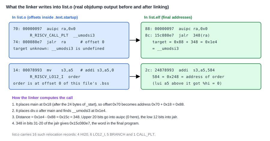
The offset 0x70 in .text.startup becomes address 0x18 + 0x70 = 0x88. __umodsi3 is at 0x1e4, so the distance from the call is 0x1e4 - 0x88 = 0x15c = 348. The upper part of that distance goes into the auipc (0 here, because the distance is small) and the lower 12 bits into the jalr, which turns 000080e7 into 15c080e7. In the same way, every %lo(order) becomes 0x248 = 584, the address the linker gave the array.
Why a Call Is Two Instructions
The compiler writes call __umodsi3, and the assembler expands it into two instructions: auipc ra,0 adds an upper immediate, shifted left by 12, to the address of the auipc itself and puts the sum in ra; jalr ra,offset(ra) jumps to ra plus a 12-bit offset and writes the return address into ra. Together they can reach any address within 2 GB in either direction, which covers the whole 32-bit address space. The single-instruction jal can reach only 1 MB in either direction, as Branches and Jumps explains. The compiler and the assembler do not know how far away __umodsi3 will be, so they must use the pair that always works.
The linker, however, does know. With linker relaxation, the default for RISC-V tools, the assembler marks each place that could be shortened with an extra R_RISCV_RELAX record, and the linker replaces long sequences by short ones once the distances are known. Linking the same program both ways shows the effect:
| Build | Relocation records in list.o | Code bytes | Call to main | Call to __umodsi3 |
|---|---|---|---|---|
-mno-relax | 16 | 584 | auipc + jalr | auipc + jalr |
| with relaxation | 27 | 568 | jal 14 <main> | jal 1d4 <__umodsi3> |
The relaxed program is 16 bytes, four instructions, shorter. Two calls became a single jal each, and two lui instructions with an upper part of 0 disappeared, because the addresses they helped build are below 4 KB and fit in the 12-bit immediate alone: addi s3,a5,584 became li s3,568, with the array now at 568 because everything before it is 16 bytes shorter. That shift is the price: every address after the first shortened instruction changes.
Some embedded projects build with -mno-relax so that the executable is the object code instruction for instruction, with only the address fields filled in. Every call then has the same two-instruction shape, and a small change in one function does not move the code of the others. The listings in these articles are built this way. A second kind of relaxation, which turns a lui and addi pair into one instruction relative to the global pointer register gp, would also need start-up code that sets gp up. Production builds usually keep relaxation on, because smaller code is also faster.
Where Does This Matter?
Every chip with an embedded processor comes with linker scripts that match its memory map: code in flash at one address, data and stack in SRAM at another, and sometimes a fast routine copied into a tightly coupled memory. Firmware teams track the size of every section in each build, because a release that overflows the flash by one byte cannot ship, and the map file shows which change caused it. Verification engineers meet the same tools when they build test programs for a processor or SoC: the test must be linked for the addresses the design really decodes.
The Executable
The linker's output, list.elf, is again an ELF file, now of type EXEC (executable) with entry point 0x0. Its program headers, printed by readelf -l, describe what to load:
  Type           Offset   VirtAddr   PhysAddr   FileSiz MemSiz  Flg Align
  LOAD           0x001000 0x00000000 0x00000000 0x00248 0x01a48 RWE 0x1000
There is one segment, a piece of the file to be placed in memory: 0x248 = 584 bytes of contents from the file, to be placed at address 0, occupying 0x1a48 = 6,728 bytes of memory. The difference, 6,728 - 584 = 6,144 bytes, is the .bss, which a loader must fill with zeros. The size tool summarizes the same numbers:
   text	   data	    bss	    dec	    hex	filename
    380	      0	   6144	   6524	   197c	/out/list.o
    584	      0	   6144	   6728	   1a48	/out/list.elf
The text grew from 380 to 584 bytes between the object file and the executable: the start-up code and the library routines were added. The .bss did not change. Programs with constant data also have a .rodata section: a small program that prints messages might have a few hundred bytes of code and a few dozen bytes of strings. The executable also carries sections that are never loaded, such as symbol tables and debug information, which is why the ELF file on disk is much larger than the program it contains.
Loading the Program
On a computer with an operating system, the loader is part of the operating system. It reads the program headers, maps each LOAD segment into the process's memory, fills the .bss part with zeros, sets up a stack and jumps to the entry point. A chip without an operating system has no such loader, and the job is split between the build flow and the start-up code: the program is copied into memory by a boot ROM, a debugger or a simulation, and crt0 prepares the rest. Boot ROM and the Boot Flow shows what start-up code must do on a real chip, including copying .data and clearing .bss.
Without an operating system, the loading path usually has three steps, shown in the picture:
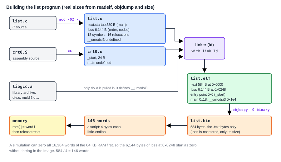
First, objcopy -O binary list.elf list.bin writes the loadable contents as raw bytes, starting at address 0: 584 bytes. The .bss is not in it, because a raw binary only holds bytes with contents. Second, a small script pads the binary to a multiple of 4 bytes and reads it as 32-bit little-endian words: 584 / 4 = 146 words, the first being 0x00010137, the encoding of lui sp,0x10. Memory is organized in words, so this is the form it needs. Third, something outside the processor does what a loader does: a flash programmer, a debugger or, during chip design, a simulation. In a simulation it can be as simple as this:
for (int i = 0; i < 16384; i++)
    ram[i] = 32'd0;                     // clear the whole 64 KB memory
for (int i = 0; i < progs.size(wl_id); i++)
    ram[i] = progs.word(wl_id, i);      // copy the program words to address 0
repeat (3) @(posedge clk);
rst_n = 1'b1;                           // release reset: the core fetches from 0
Clearing all 16,384 words first is what makes the 6,144 bytes of .bss zero, as C requires, even though they are not in the image. The processor then comes out of reset, fetches lui sp,0x10 from address 0 and runs the program exactly as the linker laid it out. How a Program Runs: Loops, Calls and the Stack follows what happens next.
Quick Check
Q: A colleague adds a global array static u32 table[256]; to list.c. Which numbers in the size output change, and does list.bin get larger?
Show Answer
The array has no initial value, so it goes into .bss: bss grows by 256 x 4 = 1,024 bytes and dec grows with it. The text does not change (unless the code that uses the array adds instructions), and list.bin does not get larger, because .bss is not stored in the image; only its address range grows, and the memory clear at start-up makes it zero.
Common Mistakes
Mistake #1: Reading object-file addresses as final addresses
A disassembly of list.o shows the call to __umodsi3 at 0x70 with a jump offset of 0; the running program has it at 0x88 with an offset of 348. Debug crashes and trace mismatches with the linked executable's listing, never the object file's.
Mistake #2: Assuming .bss is zero without start-up code
.bss takes no space in the image, so nothing writes it unless someone clears it. A simulation often gets zeros because it clears memory first; on a real chip, or when a test reuses memory from a previous run, the start-up code must clear it, or uninitialized globals start with garbage.
Mistake #3: Forgetting that the linker only takes what is missing
From an archive the linker pulls in only members that define a symbol still undefined at that point. If a library is named on the command line before the object files that need it, the link fails with "undefined reference" even though the library contains the routine. Put libraries after the objects that use them, with -lgcc at the end of the command.
Practice Exercise
Challenge: Relocate the Call to main by Hand
In crt0.o the call to main is auipc ra,0x0 at offset 0x4 and jalr ra at offset 0x8, with an R_RISCV_CALL_PLT main relocation at offset 0x4. The linker places .text.start at address 0 and main at 0x18. Compute the value the linker writes into the jalr, and the final 32-bit word, given that jalr ra with offset 0 is 000080e7 and the offset occupies bits 31 to 20. Then check how many words build.py makes from the 584-byte binary.
Hint
The offset is measured from the auipc, because auipc adds its immediate to its own address. A 12-bit offset placed in bits 31 to 20 is the offset shifted left by 20.
Solution
The auipc stays at address 0x4 (crt0 is placed at 0). The distance to main is 0x18 - 0x4 = 0x14 = 20, small enough that the auipc immediate is 0 and the whole distance goes into the jalr. 0x014 shifted left by 20 is 0x01400000, and 0x01400000 + 0x000080e7 = 0x014080e7. The linked listing shows exactly 8: 014080e7 jalr 20(ra) # 18 <main>. The binary of 584 bytes is already a multiple of 4, so build.py makes 584 / 4 = 146 words.
Summary
- The assembler turns assembly into an ELF object file with sections, a symbol table and relocation records for every address it cannot know yet.
list.oholds 380 bytes of code, a 6,144-byte.bssstored only as a size, 18 symbols (with__umodsi3undefined) and 16 relocations.- The linker resolves symbols (pulling only
div.ofromlibgcc.a), lays out memory aslink.ldsays (_startat 0) and fills in every relocation. - A call is
auipc+jalrso it can reach any address; relaxation shortens close calls tojaland saved 16 bytes in the example, but moves every later address, so some projects use-mno-relax. - Without an operating system, loading means
objcopyto a raw binary, conversion to memory words, and something that clears memory, copies the words to address 0 and releases reset.
