
A five-stage pipeline is the classic way to build a processor: five blocks of hardware in a row, each working on a different instruction, so that one instruction can finish in every clock cycle. Nearly every real processor is built on this idea, and a five-stage RISC design is the standard example. This article walks through each stage, explains the pipeline registers that make the overlap work, shows how control signals travel with their instructions, and explains why a pipeline never quite reaches one instruction per cycle.
11 min read | Beginner
What You'll Learn
- Describe what each of the five stages does and which hardware it uses
- Explain what pipeline registers hold and why they are needed
- Read a pipeline diagram and find the cycle in which each instruction does its work
- Calculate the ideal gain of a pipeline and explain what reduces it
From Steps to Stages
Single-Cycle and Multi-Cycle Processors ended with a simple observation: while one instruction uses one part of the hardware, the other parts sit idle. A pipeline lets a new instruction start as soon as the first part is free. The hardware is split into stages by inserting registers, and each stage does one step of the work. An instruction moves to the next stage on each clock edge, and a new instruction enters at the front.
The time one instruction takes does not fall. It rises slightly. What changes is how often an instruction finishes. If five instructions are in flight, then ideally one finishes in every cycle, which gives a CPI, cycles per instruction, of 1 at a clock that is about five times faster than a single-cycle design. The Instruction Cycle introduced the pipeline diagram; here we go inside it.
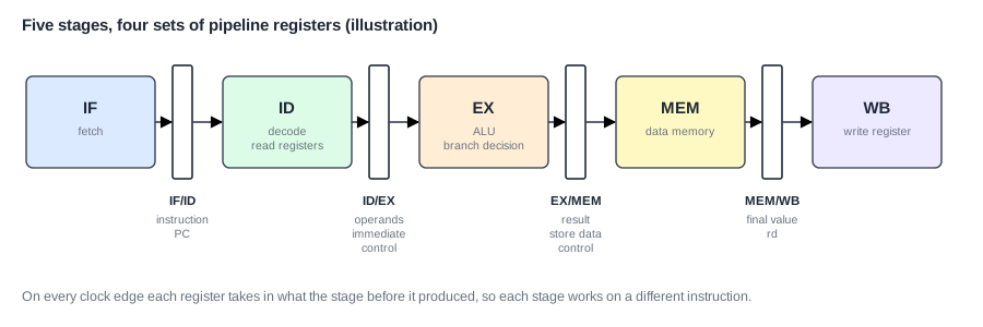
The Five Stages
IF: Instruction Fetch
The program counter (PC) sends an address to the instruction memory, and the 32-bit instruction comes back. At the same time, a small adder computes PC + 4, the usual next address. At the end of the cycle, the instruction and its PC go into the next pipeline register, and the PC takes its next value: normally PC + 4, or a branch target if the execute stage has just decided on one.
ID: Instruction Decode
The decoder looks at the opcode and produces the control signals. The register file reads the two source registers, and the immediate generator builds the 32-bit constant from the instruction's bits. One nice feature of RISC-V makes this easy: the register fields are always in the same bit positions, so the registers can be read before the decoder has finished working out what the instruction is, as RISC-V Instruction Formats and Encoding explains.
EX: Execute
The ALU computes. For arithmetic that is the result. For loads and stores it is the memory address. For branches, a comparator checks the condition and an adder works out the target. This is usually where a branch is decided, which is why a wrong branch costs two cycles in this design: two later instructions have already entered the pipeline by the time the answer is known.
MEM: Memory Access
Loads read the data memory and stores write it. Everything else just passes through. Separate instruction and data memory ports are essential here: otherwise a load in MEM and an instruction being fetched in IF would need the same memory in the same cycle. In real processors these two ports are the instruction cache and the data cache.
WB: Write Back
The result, either the ALU's value or the loaded data, is written into the destination register. Then the instruction is finished, and we say it has retired or committed.
Pipeline Registers
When five instructions share the hardware, each stage needs its own information about its own instruction. The EX stage cannot look at the instruction in decode, because by then that is a different instruction. The pipeline registers, one set between each pair of stages, solve this. On each clock edge, every set captures everything the next stage will need, and holds it steady for one cycle.
They are named after the stages on either side:
| Register | What it holds |
|---|---|
| IF/ID | the instruction and its PC |
| ID/EX | the two register values, the immediate, the PC, the register numbers and all later control signals |
| EX/MEM | the ALU result, the value to store, the destination register number and the later control signals |
| MEM/WB | the final value, the destination register number and the write enable |
Because the registers are flip-flops, they take a little time of their own: clock-to-Q delay plus setup time. That overhead is part of every cycle, however little logic the stage contains. It is why five stages do not give exactly five times the clock speed, and why endlessly adding stages stops helping, as Pipeline Depth vs Frequency shows.
Control Signals Travel With the Instruction
The decoder produces all the control signals in ID, but they are used later: the ALU operation in EX, the memory read and write in MEM, the register write in WB. So the control signals travel down the pipeline, stored in the pipeline registers, and each stage uses the ones meant for it and drops them. The rule is simple: everything about an instruction, including its destination register number, moves along with it.
That last point catches many beginners. The write in WB must use the destination register of the instruction now in WB, not the one in the instruction just fetched. If the wrong number were used, a result would land in the wrong register, which is why the register number is carried through three sets of registers.
One more bit travels too: a valid bit, which says whether the stage holds a real instruction. To cancel an instruction, the hardware simply clears its valid bit, or equivalently turns its register write and memory write signals off. The instruction becomes a bubble, an empty slot, and it passes through the rest of the stages without changing anything.
Quick Check
Q: Why must the store data travel from ID through ID/EX and EX/MEM, even though no stage changes it until MEM?
Show Answer
The register file is read in ID, but the memory write happens two stages later. By then other instructions have used the register file, so the value must be carried along with the store instruction, in the pipeline registers.
Following Instructions Through the Pipeline
A pipeline diagram has one row per instruction and one column per cycle. Here are three instructions with no connection to each other:

Read a column to see what the hardware is doing. In cycle 3, the add is in the ALU, the load is being decoded and the sub is being fetched. Read a row to see an instruction's life. Each takes five cycles, and from cycle 5 on, one finishes per cycle.
The first instruction takes 5 cycles to come out, because the pipeline starts empty. A run of n instructions therefore takes n + 4 cycles. For a real program of many thousands of instructions, those 4 cycles do not matter: the CPI approaches 1.
The Ideal Gain, and What Reduces It
In an ideal pipeline with n equal stages, the clock period is the single-cycle period divided by n, and CPI stays at 1, so the gain is exactly n. Reality takes away from this in three ways.
First, stages are not equal. The clock must fit the slowest stage. Designers spend a lot of effort balancing stages, moving logic from one to another. Second, the pipeline registers add overhead to each cycle. Third, and most importantly, instructions are not independent. These conflicts are called hazards:
- A data hazard is when an instruction needs a result that an earlier instruction has not yet finished. Data Hazards and Forwarding explains how designs handle it.
- A control hazard is when the processor does not yet know which instruction comes next, because a branch has not been decided.
- A structural hazard is when two instructions need the same hardware in the same cycle, such as one memory port for both fetch and load.
A well-designed five-stage pipeline loses surprisingly little. In one test, six small programs on a simple five-stage processor had a CPI between about 1.26 and 1.6. Almost all the loss was taken branches. A CPI of 1.5 still means two instructions finish every three cycles, at a clock several times faster than a single-cycle design could run.
Where Is This Used?
The five-stage layout came from the first RISC processors of the 1980s, and it is still the base of small embedded cores. Many 32-bit microcontroller cores use between two and seven stages, chosen by how much clock speed they need. Larger processors keep the same logical steps but split each into several stages. They may run 15 to 20 stages or more, with fetch alone taking several.
Keeping the Stages Moving: Stall and Flush
Two controls let the pipeline deal with hazards. A stall holds an instruction in its stage for an extra cycle. The registers behind it keep their values, by turning off their write enable, and a bubble is sent on ahead. A flush cancels instructions already in the pipeline, turning them into bubbles, because they turned out to be the wrong ones.
Both must obey a rule: an instruction that was canceled must never change anything a program can see. Since register writes happen only in WB and memory writes only in MEM, a wrong instruction in an early stage can be canceled with no trace. That is one of the reasons the design places these writes late. Load-Use Stalls and Control Hazards goes through both.
Quick Check
Q: A five-stage pipeline runs 1,000 instructions with no hazards at all. How many cycles does it take, and what is the CPI?
Show Answer
1,000 + 4 = 1,004 cycles, because the first instruction needs 5 cycles and each later one needs 1 more. CPI = 1,004 / 1,000 = 1.004, very close to the ideal of 1.
Common Mistakes
Mistake #1: Using a signal from the wrong stage
Each stage must use the values in the pipeline register in front of it. Reading the destination register number straight from the decoder, in WB, uses the number of a different instruction. This is the most common bug in a first pipeline.
Mistake #2: Thinking a pipeline makes each instruction faster
Each instruction takes longer, not shorter. A pipeline improves throughput. Code that depends on a single instruction's latency, such as a chain of dependent loads, gains much less.
Mistake #3: Forgetting that a canceled instruction must leave no trace
When a flush turns an instruction into a bubble, every signal that changes state must be disabled, including register write, memory write and any counter updates. Leaving one on makes a wrong-path instruction change the machine.
Practice Exercise
Challenge: Balance the Stages
A processor's work has these assumed delays: IF 300 ps, ID 200 ps, EX 350 ps, MEM 300 ps, WB 150 ps. Each pipeline register adds 50 ps. (a) What is the single-cycle period (no registers needed)? (b) What is the five-stage clock period? (c) What is the speedup at a CPI of 1.3 for the pipeline, against a CPI of 1 for single-cycle? (d) A designer moves 50 ps of logic from EX to ID. What is the new clock period?
Hint
The pipeline's clock is the longest stage plus the register overhead.
Solution
(a) 300 + 200 + 350 + 300 + 150 = 1,300 ps. (b) 350 + 50 = 400 ps. (c) Time per instruction: 1,300 ps against 1.3 x 400 = 520 ps, a speedup of 2.5. (d) EX becomes 300 ps and ID 250 ps. The longest stage is now 300 ps (IF, EX and MEM), so the period is 350 ps, 12.5 percent shorter, with no change to the logic's total delay.
Summary
- A pipeline splits the processor into stages, so that up to five instructions are worked on at once and one finishes per cycle.
- The five stages are fetch, decode, execute, memory access and write back.
- Pipeline registers carry each instruction's data, control signals and destination register number from stage to stage.
- The clock must fit the slowest stage plus the register overhead.
- Hazards, handled with stalls and flushes, keep a real pipeline's CPI above 1.
