
Before a single line of testbench code is written, a DV engineer must understand the design they are about to verify. That understanding comes from one primary source: the DUT specification. A specification is not just background reading — it is the legal contract between the design team and the verification team, and ultimately between the chip designer and the chip's users. Every test scenario, every scoreboard check, and every coverage point traces back to something the specification says should be true. Reading a spec correctly is therefore one of the most important practical skills a DV engineer develops.
11 min read | Intermediate Level
What You'll Learn
- What sections a DUT specification typically contains and what each one provides
- How to extract verifiable features from prose and translate them into test scenarios
- How to identify and handle ambiguous or underspecified behaviour
- What register map verification involves and what the scoreboard uses the spec for
What a DUT Specification Contains
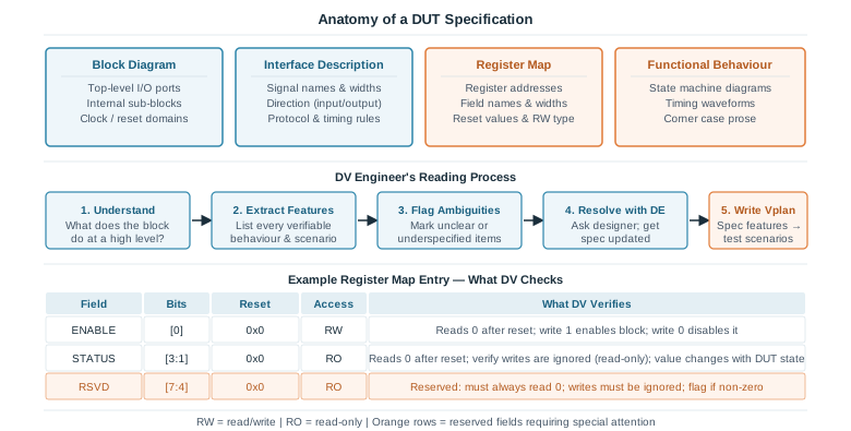
A DUT specification — sometimes called a design spec, block spec, or micro-architecture document — describes what a design block is supposed to do in enough detail for both the design engineer and the DV engineer to work from it independently. Specs vary widely in quality and format across companies, but most contain the same core sections.
Block Diagram
The block diagram gives a visual overview of the design: its top-level input and output ports, any major internal sub-blocks, and the clock and reset domains it operates in. For the DV engineer, the block diagram answers the first question: what does this block connect to and what signals does it expose? The list of ports from the block diagram becomes the starting point for the testbench interface definition.
Interface Description
The interface section describes every signal in detail — name, direction, bit width, and the protocol or timing rules that govern it. For a block with an AXI slave interface, this section will describe every channel (AW, W, B, AR, R), every signal within each channel, and the handshake rules that govern when signals are valid. This is the section the DV engineer returns to repeatedly when building the driver and monitor.
Register Map
The register map is a table listing every software-accessible register in the block: its address offset, the fields within it (name, bit position, width), the reset value of each field, and the access type (read-write, read-only, write-only, write-one-to-clear, and so on). Register maps are some of the most mechanically verifiable parts of a spec — each field has a precise expected behaviour that can be checked with a directed test. Register map verification is covered in detail later in this article.
Functional Behaviour
The functional behaviour section is usually the longest and most complex part of the spec. It describes the design's operation in prose, state machine diagrams, timing waveforms, and pseudocode. This is where the DV engineer spends the most time, because this is where the interesting corner cases live — back-to-back transactions, error recovery sequences, priority arbitration under simultaneous requests, and pipeline interactions that are hard to infer from the interface description alone.
Specifications are written by human beings under schedule pressure. They are often incomplete, occasionally contradictory, and sometimes just wrong. A DV engineer who treats the spec as perfect and infallible will build a testbench with the same flaws baked in. Reading critically — and asking questions — is part of the job.
Extracting Verifiable Features From Prose
The functional behaviour section of a spec is written to explain the design to a reader. It is not written to generate test cases. Translating prose description into a list of verifiable features is a skill that takes practice, but it follows a consistent pattern.
The process is to read each paragraph and ask: what claim is this making about the design's output or behaviour? Every claim is a potential test scenario. Consider the following example spec excerpt for a simple FIFO controller:
"When the FIFO reaches its maximum depth of 16 entries, the full flag is asserted. Any write request received while full is asserted is silently dropped. The full flag is de-asserted on the clock cycle following a successful read."
From three sentences, a DV engineer extracts at least five test scenarios:
- Write 16 entries and confirm <full asserts on the 16th write
- Attempt a write while <full is asserted and confirm the entry count does not increase
- Confirm no error flag or interrupt fires when a write is dropped (the spec says "silently")
- Read one entry from a full FIFO and confirm <full de-asserts exactly one cycle later
- Simultaneous read and write while full — not mentioned in the excerpt, which itself is an ambiguity to raise
This extraction process — reading prose, listing claims, identifying implied corner cases — is applied to every section of the spec. The output feeds directly into the Vplan as a list of features and scenarios.
Quick Check
Q: A spec says: "The arbiter grants bus access to the highest-priority requester. If two requesters of equal priority assert simultaneously, the arbiter grants access to the lower-indexed requester." List at least three test scenarios this implies.
Show Answer
1. Single requester asserts — confirm it receives the grant.
2. Two requesters of different priority assert simultaneously — confirm the higher-priority one receives the grant.
3. Two requesters of equal priority assert simultaneously — confirm the lower-indexed one receives the grant.
4. (Bonus) Three or more requesters assert simultaneously, including at least one equal-priority pair — confirm priority and tie-breaking both apply correctly.
5. (Bonus) A high-priority requester asserts while a lower-priority requester already holds the grant — spec does not say what happens. This is an ambiguity to raise with the design engineer.
Identifying and Handling Ambiguities
An ambiguity in the spec is a statement that can be interpreted in more than one way, or a scenario the spec does not address at all. Both types are dangerous: if the DV engineer and the RTL design engineer interpret the spec differently, the testbench will have a different model of correct behaviour from the RTL — and both will pass their own checks without either catching the other's assumption.
Types of Ambiguity
Undefined behaviour: The spec describes normal operation but does not state what the design should do in an error case. For example: "The block processes one transaction per clock cycle" — but what happens if a second transaction arrives before the first has been acknowledged? The spec may simply not say.
Contradictory statements: Two sections of the spec make incompatible claims. For example, the interface table says a signal is active-high, but a timing diagram in the functional section shows it asserted low. These are common in large specs that have been edited by multiple authors.
Ambiguous timing: The spec says something happens "after" an event without specifying how many clock cycles later. "The acknowledge signal is asserted after the request is received" — on the same cycle? The next cycle? After an arbitrary number of cycles?
How to Handle Ambiguities
The correct response to an ambiguity is never to assume. The DV engineer should:
- Log it explicitly — keep a running list of ambiguities found during spec reading, with the exact sentence that is unclear and the different interpretations it permits
- Ask the design engineer directly — a five-minute conversation resolves most ambiguities faster than any amount of inference
- Get the spec updated — the resolution should be written back into the specification, not just held in an email thread or a verbal agreement. An ambiguity that is resolved in conversation but not captured in the spec will confuse the next engineer who reads it
- Note the assumption in the Vplan — if the spec cannot be updated immediately, document the assumption explicitly in the Vplan so it can be reviewed and corrected
Never resolve a spec ambiguity by looking at the RTL and testing to match whatever the design happens to do. The RTL may itself contain the bug — the design engineer may have made the same incorrect assumption you are trying to avoid. The spec, corrected and agreed upon, is the only valid ground truth.
Register Map Verification
The register map is one of the most systematically verifiable parts of any design. Unlike functional behaviour — which often requires complex stimulus sequences to exercise — register checks can be written as straightforward directed tests, and most of them can be automated from the register map table itself.
Reset Value Verification
After reset de-asserts, every register field must contain its specified reset value. This is verified by reading every register immediately after reset and comparing each field against the spec table. A field reading 0x1 when the spec says its reset value is 0x0 is a genuine RTL bug — and one of the most common.
Read/Write Attribute Verification
Each field has an access type. The most common types and what DV checks for each are:
| Access Type | Abbreviation | What DV Verifies |
|---|---|---|
| Read-Write | RW | Write a value, read it back — value must match. Write 0 and 1 separately to confirm both stick. |
| Read-Only | RO | Write any value — field must not change. Read the field at appropriate times to confirm it reflects hardware state correctly. |
| Write-Only | WO | Read always returns 0 (or a defined value). Write a value and confirm the intended hardware action occurs even though the value cannot be read back. |
| Write-1-to-Clear | W1C | Field is set by hardware (e.g. an interrupt flag). Writing 1 clears it; writing 0 has no effect. Verify both: that a 1-write clears, and that a 0-write does not. |
| Reserved | RSVD | Must always read 0. Writes must be ignored. Check that writing non-zero values does not corrupt adjacent fields. |
Field Behaviour Verification
Beyond reset values and access types, functional fields change in response to hardware events. A status field that reflects the current state of a state machine must be read at each state transition and compared against the spec. An interrupt flag that sets when a FIFO overflows must be verified by triggering an overflow and reading the flag. Each of these is a scenario in the Vplan.
Most companies have a register model (built in UVM's Register Abstraction Layer, or RAL) that is auto-generated from the register map table. This automates reset-value checks and basic RW tests. However, auto-generated tests alone are not sufficient — they do not verify field behaviour in response to hardware events, which must be written manually.
Using the Spec as Scoreboard Ground Truth
The scoreboard — the testbench component that checks DUT outputs against expected values — must have a model of what correct behaviour looks like. That model comes from the spec. In practice, this means:
Reference model: For blocks with complex output transformations (a hash engine, a packet parser, a DMA controller), the DV engineer writes a reference model — a behavioural description of the expected output for a given input — based entirely on the spec. The scoreboard compares the DUT's output against the reference model's output for the same input. If they differ, the scoreboard fires.
Protocol checkers: For interface protocols, the spec defines the handshake rules. SVA assertions in the testbench encode these rules and fire whenever the DUT violates them. Every assertion traces back to a specific sentence in the spec.
Register checks: After a register write, the scoreboard can predict what value a subsequent read should return, based on the access type in the register map. This prediction comes from the spec, not from observing what the DUT does.
A scoreboard built by observing the DUT's behaviour and checking that it is self-consistent — rather than checking against the spec — is one of the most dangerous testbench patterns. It will pass every test even when the DUT is wrong, as long as it is consistently wrong. The spec is the only valid reference.
Quick Check
Q: A DV engineer writes a scoreboard for a CRC generator block. Rather than implementing the CRC algorithm from the spec, they capture the DUT's first output and use it as the expected value for all subsequent runs. What is wrong with this approach?
Show Answer
The scoreboard is checking self-consistency, not correctness. If the DUT's CRC implementation is wrong — computing the wrong polynomial, inverting the output, or using the wrong initial seed — the scoreboard will accept that wrong value as correct on the first run and pass all subsequent tests. The correct approach is to implement the reference CRC algorithm from the spec independently in the scoreboard, so that any deviation between the spec and the DUT output is detected, regardless of whether the deviation is consistent.
Practical Tips for Reading a New Spec
Reading a new specification efficiently is a skill developed over multiple projects. A few habits that help:
- Read the block diagram first, then the interface table, then the functional behaviour. Starting with functional prose before understanding the port list makes it harder to build a mental model of the block. The block diagram and interface table provide the scaffolding that makes the functional description interpretable.
- Annotate as you read. Mark every claim that implies a test, every ambiguity that needs resolution, and every corner case mentioned in passing. A spec read without annotation produces a weak Vplan because the engineer's memory of what they noticed will fade.
- Read the register map like a checklist. Go field by field, not register by register. For each field, ask: is the reset value testable? Is the access type clearly defined? Does the functional section describe when this field changes?
- Look for what the spec does not say. Errors of omission — scenarios the spec silently ignores — are at least as dangerous as contradictions. If the spec only describes the happy path, the DV engineer must explicitly ask: what happens in the error cases?
Common Mistakes
Mistake 1: Assuming the spec is complete and correct.
Wrong: Reading the spec once, treating every statement as authoritative, and building the Vplan without logging any questions or ambiguities.
Right: Read the spec actively and critically. Log every ambiguity, contradiction, and undefined scenario. Resolve them with the design engineer before writing testbench code.
Why? A spec-faithful testbench built on a flawed spec will miss the same bugs as the RTL built on the same flawed spec. The spec is the starting point for verification quality — errors there propagate everywhere.
Mistake 2: Skipping register map verification because "it's just register reads and writes."
Wrong: Treating register map checks as low-value boilerplate and deprioritising them in favour of functional tests.
Right: Run reset-value, access-type, and field-behaviour checks as a foundational part of the verification plan. Register bugs are among the most common and most visible failures in silicon bring-up.
Why? Software running on the chip configures it through registers. A register that does not reset correctly, or whose write is silently ignored, causes failures in firmware that are extremely hard to debug post-silicon because they look like software bugs rather than hardware bugs.
Mistake 3: Resolving spec ambiguities by reading the RTL.
Wrong: When the spec is unclear about a behaviour, opening the RTL to see what the design actually does and writing the testbench to match.
Right: Raise the ambiguity with the design engineer, agree on the correct behaviour, and update the spec before writing any testbench code.
Why? The RTL may contain the bug. If the designer made an incorrect assumption about the same ambiguity, their RTL implements that assumption — and a testbench written to match the RTL will pass even when both are wrong. Only an independently resolved spec can expose this class of bug.
Practice Exercise
Challenge: Extract and Evaluate
Read the following excerpt from a hypothetical DUT specification for a watchdog timer block, then answer the questions below.
"The watchdog timer counts down from the value loaded in the TIMEOUT register. When the counter reaches zero, the WDT_INT interrupt flag is set and a reset pulse is issued to the system. Writing any value to the KICK register reloads the counter to the TIMEOUT value. The WDT_INT flag is cleared by writing 1 to bit 0 of the STATUS register."
- List at least five test scenarios implied by this excerpt.
- Identify at least two ambiguities or underspecified behaviours that need to be resolved before writing a testbench.
- For the WDT_INT flag, what access type does the STATUS register bit 0 appear to be?
Hint
For scenarios, think about each sentence separately and what it implies. For ambiguities, look for things the spec says happen but does not fully define — timing, edge cases at boundaries, simultaneous events.
Sample Answer
Test scenarios:
1. Load a value into TIMEOUT, let the counter expire, confirm WDT_INT is set.
2. Let the counter expire, confirm a reset pulse is issued to the system.
3. Write to KICK before the counter expires, confirm the counter reloads to TIMEOUT value.
4. Write 1 to STATUS[0] after WDT_INT is set, confirm the flag clears.
5. Write 0 to STATUS[0] while WDT_INT is set, confirm the flag does not clear (W1C semantics).
6. Write to KICK exactly when the counter reaches zero — simultaneous expire and kick. Spec does not define this — flag as ambiguity.
Ambiguities:
1. How wide is the TIMEOUT register? What is its reset value? Can TIMEOUT be zero, and if so, does the watchdog fire immediately on enable?
2. The spec says a reset pulse is issued — how long is the reset pulse? Is the system reset synchronous or asynchronous to the watchdog clock? Is there a way to disable the reset pulse and keep only the interrupt?
3. What happens if KICK is written while a reset pulse is already being issued?
Access type:
STATUS[0] / WDT_INT appears to be W1C (Write-1-to-Clear) — the hardware sets it (on timeout), writing 1 clears it, and writing 0 has no effect.
Summary
In this article, you learned:
- A DUT specification contains four main sections: block diagram, interface description, register map, and functional behaviour — each provides different inputs to the Vplan and testbench
- Verifiable features are extracted from prose by identifying every claim the spec makes about output or behaviour, then asking what scenarios exercise each claim
- Ambiguities must be resolved with the design engineer and written back into the spec — never by assuming or by reading the RTL
- Register map verification covers reset values, access types, and field behaviour — it is systematic, high-value, and partially automatable through UVM RAL
- The scoreboard and reference model must be built from the spec, not derived from DUT behaviour — a self-consistency check is not a correctness check
