
A simulation failure gives you one piece of information: something went wrong, at some point, in some signal. Turning that single data point into a fixed RTL bug is a skill built on systematic methodology. Engineers who debug randomly — opening waveforms and browsing signals hoping to spot something unusual — waste hours. Engineers with a structured approach work through the same failures in minutes. This article covers the two core debugging techniques: divide and conquer to find when the bug occurs, and signal tracing to find where in the logic it originates.
9 min read | Intermediate Level
What You'll Learn
- How to bisect a simulation timeline to rapidly narrow the failing window
- How to trace a wrong signal backward through logic to its root cause
- How assertions act as proximity detectors that fire close to the bug source
- How to reproduce intermittent failures and recognise common bug categories
Divide and Conquer
A simulation that runs for a million clock cycles and fails somewhere in the middle presents a navigation problem before it presents a logic problem. You need to know when the design first went wrong before you can understand why. The divide-and-conquer technique solves this with binary bisection: rather than scanning from the beginning, you check the midpoint of the simulation, determine which half contains the earliest failure, discard the other half, and repeat.
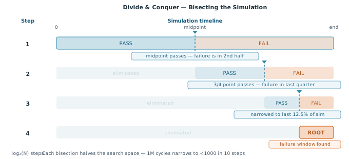
In practice, bisection works by inserting a temporary assertion or checkpoint at the halfway point of the simulation and running to that point. If the design state looks correct there, the bug is in the second half — discard the first half and bisect the remainder. If the design state is already wrong, the bug is in the first half. Each iteration halves the search space. Ten bisections narrow one million cycles to fewer than a thousand. This is far faster than scrolling through a waveform from cycle zero.
You do not always need to run the full simulation to check a midpoint. Many simulators support saving a simulation snapshot — a checkpoint of the complete design state at a given time — that you can restore and continue from without re-running the earlier portion. Check your simulator's documentation for checkpoint and restore commands.
Bisection also applies at a higher level. If a test suite has hundreds of tests and one regression run produces failures across several of them, start by checking whether the failures share a common time window or a common design block. A failure that appears in every test involving the memory interface is not ten independent bugs — it is one bug in the memory interface that manifests across ten tests.
Signal Tracing
Once you have narrowed the failure to a specific time window, signal tracing finds the root cause. The fundamental rule is: start at the wrong output and follow the fanin backward. Never start at a suspected cause and look forward — you will waste time on signals that were not involved.
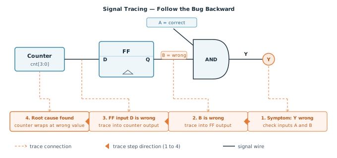
The trace follows a repeating pattern at each level of logic:
- Identify the wrong signal. You have a signal whose value is incorrect at the timestep of interest. This is your starting point.
- Check its inputs. For a combinational gate, look at all the input signals at the same timestep. For a register, look at its data input at the previous clock edge.
- Find which input is wrong. One or more inputs will be incorrect. Mark the correct ones and continue tracing only the wrong one.
- Repeat one level back. The wrong input becomes your new starting signal. Check its inputs. Keep going until you find a signal that is wrong but whose inputs are all correct — that is the root cause.
The trace terminates when you reach a signal that is wrong despite having all-correct inputs. At that point, the bug is in the logic that computes that signal — a wrong condition in an if statement, a missing reset, an off-by-one in a counter, or a wrong operator in an expression.
Tracing through a register requires stepping back one clock cycle. If a register output is wrong at cycle N, its input was wrong at cycle N-1 (the cycle when the register sampled its data input). Always account for this cycle boundary when tracing through sequential elements.
Quick Check
Q: You are tracing a wrong output signal. You find that it is driven by an OR gate. Both inputs to the OR gate are correct at the relevant timestep. Where is the bug?
Show Answer
The bug is in the OR gate itself — or more likely, in the RTL that describes it. If both inputs are correct and the output is wrong, the logic expression computing the output is wrong. Check the RTL: is it actually an OR gate, or should it be an AND, XOR, or some other operation? A common cause is a typo (| vs &) or a wrong operator in a complex boolean expression.
Using Assertions as Bug Proximity Detectors
The further a failure propagates through a design before being caught, the harder it is to trace back to its source. A wrong value in a counter on cycle 100 may not produce a visible wrong output until cycle 850, by which point the waveform contains hundreds of cycles of corrupted state to sift through. Assertions solve this by checking invariants directly in the RTL, close to the logic they monitor, so that violations fire at or near the cycle the bug actually occurred.
There are two kinds of assertions in SystemVerilog:
- Immediate assertions fire when the line of code executes, inside a procedural block. They check a condition at a specific point of execution and are useful for verifying assumptions about values mid-computation.
- Concurrent assertions evaluate at every clock edge and express temporal properties — things that must be true about signal relationships over time. They are written outside procedural blocks and are the primary tool for protocol checking and invariant monitoring.
// Immediate assertion — fires when this line executes
always @(posedge clk) begin
    count <= count + 1;
    assert (count < MAX_COUNT)
        else $error("[%0t] count overflow: %0d", $time, count);
end

// Concurrent assertion — evaluates every clock edge
assert property (@(posedge clk) valid |-> !$isunknown(data))
    else $error("[%0t] data is X while valid is asserted", $time);
When an assertion fires, the error message appears in the log with a timestamp. That timestamp is the start of your divide-and-conquer search — not the end of the simulation, but the cycle the property was first violated. This is almost always much closer to the actual root cause than a scoreboard mismatch caught thousands of cycles later.
Adding assertions to RTL is not only a debugging technique — it is a verification technique. A well-asserted design catches bugs at their source during any simulation, not just when you happen to be actively debugging. Assertions added during debug should be kept in the RTL permanently so they protect against future regressions.
Reproducing Failures
A failure you cannot reproduce reliably is a failure you cannot debug. Two categories of simulation failures require special attention for reproduction:
Seed-dependent failures arise in tests that use constrained random stimulus. Each run uses a different random seed to generate its input transactions, so the same test may pass with seed 42 and fail with seed 1983. When a failure is found, record the seed immediately — it is printed in the simulator log at the start of every run. To reproduce the failure deterministically, re-run with the same seed using your simulator's +ntb_random_seed or equivalent plusarg. Once you have a reproducible run, you can use divide and conquer and signal tracing normally.
// Re-run with a specific seed (simulator-dependent syntax)
// Cadence:   +ntb_random_seed=1983
// Synopsys:  +ntb_random_seed=1983
// Mentor:    -sv_seed 1983
Race-condition failures may disappear when you add $display statements or change the simulation options, because those changes alter the Active-region scheduling order. If a bug only appears sometimes and vanishes when you try to instrument it, suspect a race condition of the kind described in article 4.2. The fix is to eliminate the race in the testbench rather than to chase the symptom.
Common Bug Categories and Their Signatures
Certain classes of RTL bugs appear repeatedly across designs and have recognisable waveform signatures. Learning these patterns shortens the trace significantly.
Off-by-one errors are the most common category in counter and FSM logic. A counter that should wrap at value N wraps at N-1 or N+1. Symptoms: a burst that is one transaction too long or too short; a FIFO that overflows by one entry; a timer that expires one cycle early. Look for comparators using < vs <= or a reset value that is 0 vs 1.
Missing or incorrect reset causes registers to start in state X and propagate unknown values until something forces them to a known state. Symptom: X values appearing at the start of simulation that do not resolve after reset deasserts, or output signals that behave correctly in some runs and produce X in others depending on initial state. Check that every register that needs a defined reset value has an active reset condition in its always block.
Wrong clock domain bugs arise when a signal is sampled by a register clocked on a different domain without a synchroniser. In RTL simulation, CDC bugs are largely invisible — zero-delay simulation has no propagation delays, so there are no setup or hold violations. The receiving register simply captures whatever value the signal holds at the clock edge and the simulation passes cleanly. The bug only becomes apparent in gate-level simulation with SDF back-annotation, where real timing is modelled and setup/hold violations cause the register output to go to X, or in silicon where metastability can cause the device to malfunction. This is why dedicated CDC static analysis tools are used alongside simulation rather than relying on simulation alone to catch these issues.
Timing violations in gate-level simulation appear as X values on register outputs caused by setup or hold time violations flagged in the SDF-annotated netlist. These indicate that the synthesised design has a timing path that does not meet the target frequency. They are not RTL bugs — they are timing closure issues that require either RTL restructuring or physical design changes.
Where This Matters in Practice
In a typical block-level verification project, off-by-one and missing-reset bugs account for a disproportionately large fraction of the total bug count, precisely because they are easy to introduce and can hide for many cycles before producing visible symptoms. Engineers who learn to recognise these signatures early in a trace — seeing an X that never resolves, or a counter that wraps one cycle too early — eliminate entire categories of investigation before looking at anything else.
Quick Check
Q: A test fails intermittently: it passes when run with seed 100 but fails with seed 2047. You record seed 2047 and re-run. The failure now happens at cycle 48,320 out of 100,000 total cycles. What is your next step?
Show Answer
Use divide and conquer to narrow the failing window. Check the design state at cycle 24,160 (the midpoint between 0 and 48,320). If the state looks correct there, bisect between 24,160 and 48,320. Continue bisecting until you have narrowed the window to a few hundred cycles, then open the waveform at that point and begin signal tracing backward from the wrong output.
Common Mistakes
Mistake 1: Starting signal tracing from a suspected cause rather than the confirmed symptom.
Wrong: "I think the bug is in the state machine, let me check the state register first."
Right: Start at the confirmed wrong output signal and trace its fanin backward. Let the logic tell you where the bug is.
Why? Intuition about where a bug lives is wrong more often than it is right, especially in unfamiliar RTL. Starting from a hunch wastes time investigating correct logic. Starting from the confirmed wrong signal guarantees you are on the path to the root cause.
Mistake 2: Forgetting to account for register latency when tracing backward through sequential elements.
Wrong: Checking a register's data input at the same cycle the wrong output appears.
Right: Check the data input one cycle earlier — the cycle in which the register sampled and captured the wrong value.
Why? A register's output at cycle N reflects what its data input was at cycle N-1 (or whenever the capturing clock edge occurred). Checking the input at cycle N means looking at data that has not yet been captured — the wrong cycle entirely.
Mistake 3: Discarding a seed that revealed a bug before the bug is fixed and regression-locked.
Wrong: Fixing the bug, re-running, seeing the test pass, and moving on without saving the failing seed.
Right: Add the failing seed as a permanent directed regression test so the same bug cannot be reintroduced silently.
Why? A seed that found a real bug is a valuable regression asset. Without it, a future RTL change that reintroduces the same bug will only be caught if the same seed happens to be re-used in a random regression run — which may not happen until after tapeout.
Practice Exercise
Challenge: Plan the Debug Approach
A test runs for 200,000 clock cycles and produces a scoreboard mismatch at cycle 187,450. The test uses a random seed. Describe, step by step, how you would approach debugging this failure. Your answer should cover: how you would narrow the time window, which signals you would add to the waveform, and how you would begin the signal trace.
Hint
Think about what information you have (the cycle of the mismatch, the seed) and what you need (the cycle the bug first occurred, the signal that first went wrong). Work backwards from what you know.
Solution
A structured approach:
- Record the seed from the simulation log immediately so you can reproduce the exact failure deterministically.
- Bisect the timeline. Check the design state at cycle 93,725 (half of 187,450). If correct, the bug originated between 93,725 and 187,450. Bisect that window. Continue until narrowed to a few hundred cycles — typically 8 to 10 bisections.
- Open the waveform at the narrowed window. Add clock, reset, the scoreboard's expected and actual signals, and the interface signals at the boundary of the block that produced the mismatch.
- Begin the signal trace. Find the first cycle where the actual output diverges from expected. That is your symptom signal. Check its inputs at the previous clock edge. Find which input is wrong and trace it back one level. Repeat until you reach a signal that is wrong with all-correct inputs — that is the RTL bug.
- Check for assertions in the log between the bisected window and the mismatch cycle. An assertion firing earlier than the mismatch is a closer starting point for the trace.
Summary
- Divide and conquer bisects the simulation timeline to locate the failing window in logarithmic time — ten bisections narrow one million cycles to under a thousand
- Signal tracing starts at the confirmed wrong output and follows fanin backward, one level at a time, until reaching a signal that is wrong despite all-correct inputs — that is the root cause
- Assertions act as proximity detectors by checking invariants close to the logic they monitor, firing at the cycle of the violation rather than cycles later when a downstream symptom appears
- Always record failing seeds immediately; seed-dependent failures are only reproducible if the seed is preserved before moving on
