
A UART transmitter turns a byte into a frame on a single wire: a start bit, eight data bits least significant bit first, an optional parity bit and a stop bit, each held for exactly one bit time. In hardware that is a small state machine, a shift register and a counter that measures the bit time in clock cycles. This article builds one with a valid/ready input, parity, and a clear-to-send input for flow control.
8 min read | Intermediate
What You'll Learn
- Derive the bit-time counter from the clock and baud rate
- Build the transmitter state machine: IDLE, START, DATA, PARITY, STOP
- Hand bytes to the transmitter with a valid/ready handshake
- Add parity and a CTS input
The Plan
- A counter
cntruns from 0 toCLKS_PER_BIT- 1 for every bit.CLKS_PER_BITis the clock frequency divided by the baud rate. - A shift register holds the byte; its bit 0 is the next data bit, and it shifts right after every data bit.
- A state machine walks through START, eight DATA bits, an optional PAR bit, and STOP.
- The byte comes in through
valid/ready, the same handshake as AXI4-Stream: the transmitter is ready only when idle.
The RTL
// UART transmitter: 8 data bits, LSB first, optional parity, one stop bit.
//   CLKS_PER_BIT  clock cycles per bit (clock frequency / baud rate)
//   PARITY        0: none, 1: even, 2: odd
// A byte is handed over with valid/ready. cts_n low means the receiver may be sent to.
module uart_tx #(
  parameter CLKS_PER_BIT = 16,
  parameter PARITY       = 0
) (
  input            clk,
  input            rst,
  input      [7:0] data,
  input            valid,
  output           ready,
  input            cts_n,                // clear to send, active low; tie low if unused
  output reg       tx
);
  localparam IDLE = 3'd0, START = 3'd1, DATA = 3'd2, PAR = 3'd3, STOP = 3'd4;

  reg [2:0]  state;
  reg [15:0] cnt;                        // clock cycles within the current bit
  reg [2:0]  bit_idx;
  reg [7:0]  shreg;
  reg        par;                        // running parity of the data bits

  wire bit_done = (cnt == CLKS_PER_BIT - 1);

  assign ready = (state == IDLE) && !cts_n;

  always @(posedge clk) begin
    if (rst) begin
      state <= IDLE;
      tx    <= 1'b1;                     // the line idles high
      cnt   <= 16'd0;
    end
    else begin
      case (state)
        IDLE: begin
          tx <= 1'b1;
          if (valid && ready) begin
            shreg <= data;
            par   <= (PARITY == 2);       // odd parity starts at 1
            cnt   <= 16'd0;
            state <= START;
          end
        end
        START: begin
          tx <= 1'b0;                    // start bit
          if (bit_done) begin
            cnt     <= 16'd0;
            bit_idx <= 3'd0;
            state   <= DATA;
          end
          else begin
            cnt <= cnt + 16'd1;
          end
        end
        DATA: begin
          tx <= shreg[0];                // least significant bit first
          if (bit_done) begin
            cnt   <= 16'd0;
            par   <= par ^ shreg[0];
            shreg <= shreg >> 1;
            if (bit_idx == 3'd7)
              state <= (PARITY != 0) ? PAR : STOP;
            else
              bit_idx <= bit_idx + 3'd1;
          end
          else begin
            cnt <= cnt + 16'd1;
          end
        end
        PAR: begin
          tx <= par;                     // makes the count of ones even (or odd)
          if (bit_done) begin
            cnt   <= 16'd0;
            state <= STOP;
          end
          else begin
            cnt <= cnt + 16'd1;
          end
        end
        default: begin                   // STOP
          tx <= 1'b1;                    // stop bit
          if (bit_done) begin
            cnt   <= 16'd0;
            state <= IDLE;
          end
          else begin
            cnt <= cnt + 16'd1;
          end
        end
      endcase
    end
  end
endmodule
A few details matter:
- The output is a register.
txis assigned inside the clocked block, so the line never glitches, which matters because the receiver treats any low pulse as a possible start bit. - The line idles high after reset and between frames.
- Parity is accumulated as the bits go out:
parstarts at 0 for even parity or 1 for odd parity and is XORed with every data bit. The parity bit then makes the total number of ones even (or odd). - CTS only gates
ready: a frame that has started always completes, and the next one waits untilcts_nis low.
Quick Check
Q: The system clock is 48 MHz and the baud rate 115200. What is CLKS_PER_BIT, and how large is the timing error?
Show Answer
48,000,000 / 115,200 = 416.67, so 417 cycles. The actual baud rate is 48 MHz / 417 = 115,108, an error of about 0.08 percent, far inside what a UART tolerates.
The Simulation
The testbench hands three bytes to the transmitter and lets a receiver on the other end of the wire decode them:
task send(input [7:0] b);
  begin
    data  <= b;
    valid <= 1;
    @(posedge clk);
    while (!ready)
      @(posedge clk);
    valid <= 0;
    $display("%0t  tx sends 0x%h", $time, b);
  end
endtask
25  tx sends 0x4b
1595  rx got   0x4b
1635  tx sends 0x55
3205  rx got   0x55
3245  tx sends 0xa3
4815  rx got   0xa3
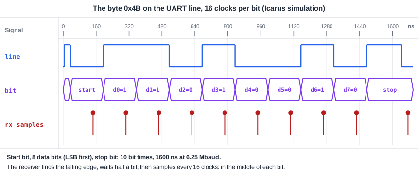
The second byte is handed over at 1635 ns, when the transmitter returns to IDLE after the stop bit of the first. With a valid/ready input the caller simply waits; a real design usually puts a small FIFO in front of the transmitter so that software can write several bytes at once.
Quick Check
Q: Why does the transmitter shift the register right and send bit 0, rather than shifting left and sending bit 7?
Show Answer
UART sends the least significant bit first, so bit 0 must go out first. Shifting right moves bit 1 into position 0 for the next data bit.
Running It in ChipVerify Lab
The example contains the transmitter, a receiver and the loopback testbench. Change the bytes and check them in the waveform, bit by bit.
Common Mistakes
Mistake #1: Counting CLKS_PER_BIT + 1 cycles
A counter that runs from 0 to CLKS_PER_BIT inclusive makes every bit one cycle too long. The error adds up over the frame, like a wrong baud rate.
Mistake #2: A combinational tx output
Decoding tx from the state with logic can glitch low between states. The receiver may take the glitch for a start bit. Drive the line from a flip-flop.
Mistake #3: Accepting a new byte mid-frame
A transmitter that loads a new byte while sending overwrites the shift register and corrupts the frame. Accept a byte only in IDLE, or add a holding register.
Practice Exercise
Challenge: Two Stop Bits
Some devices need two stop bits. Change the STOP state so that it holds the line high for two bit times, and predict when each byte is handed over.
Hint
Only the end condition of the STOP state changes: count to twice the bit time.
Solution
default: begin                   // STOP
  tx <= 1'b1;                    // stop bits
  if (cnt == 2 * CLKS_PER_BIT - 1) begin   // two bit times
    cnt   <= 16'd0;
    state <= IDLE;
  end
  else begin
    cnt <= cnt + 16'd1;
  end
end
25  tx sends 0x4b
1595  rx got   0x4b
1795  tx sends 0x55
3365  rx got   0x55
3565  tx sends 0xa3
5135  rx got   0xa3
Each frame is now 11 bit times, 1760 ns, so the next byte is handed over 160 ns later than before. The receiver, which expects one stop bit, still decodes every byte: a longer stop period just looks like a slightly longer idle line.
Open the ready-made example in the lab and run the simulation.
Summary
- A UART transmitter is a counter for the bit time, a shift register and a state machine.
CLKS_PER_BIT= clock frequency / baud rate; small rounding errors are harmless.- Data goes out least significant bit first, from bit 0 of a right-shifting register.
- Parity is accumulated with XOR as the bits go out.
- Drive
txfrom a flip-flop and accept new bytes only when idle.