
When a processor writes to address 0x4000_1000, exactly one block in the chip must react: the UART's transmit register, say, and nothing else. A memory map assigns every block its range of addresses, and an address decoder turns that map into hardware. This article builds the decoder for the teaching bus, shows the classic decoding mistake, aliasing, in a simulation, and explains how unmapped addresses are handled.
8 min read | Beginner
What You'll Learn
- Read and design a memory map
- Implement an address decoder from upper address bits
- Explain full and partial decoding and the aliasing that partial decoding causes
- Handle unmapped addresses with a default response
The Memory Map
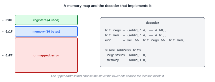
A memory map lists the address ranges and what lives in each. For a real chip it is a document with hundreds of lines; software uses it to find each register, and hardware uses it to build the decoder. The teaching bus has a map with three entries:
Two conventions make maps easy to decode:
- Each region is a power of two in size: 16 bytes here, typically 4 KB per peripheral in a real chip.
- Each region starts at a multiple of its size, called natural alignment.
With both, the upper address bits alone select the slave, and the lower bits select the location inside it. For the teaching bus, addr[7:4] picks the region and addr[3:0] the byte.
Quick Check
Q: A peripheral region is 4 KB starting at 0x4000_3000. Which address bits select the peripheral, and which select a register inside it?
Show Answer
4 KB is 212 bytes, so bits 11 to 0 select the register inside the peripheral and bits 31 to 12 must equal 0x40003 to select it.
The Decoder
The decoder compares the upper bits with each region's base and produces one select line per slave. The read multiplexer uses the same decision to route the selected slave's response back to the master:
wire hit_regs = (addr[7:4] == 4'h0);
wire hit_mem  = (addr[7:4] == 4'h1);

assign rdata = hit_regs ? rd_regs  :
               hit_mem  ? rd_mem   : 8'h00;
assign ready = hit_regs ? rdy_regs :
               hit_mem  ? rdy_mem  : 1'b1;     // unmapped: complete at once ...
assign err   = sel && !hit_regs && !hit_mem;   // ... with an error
Each slave receives sel && hit_x as its own select, and only the address bits it needs: the register slave gets addr[1:0] for its four registers, the memory gets addr[3:0].
Full and Partial Decoding
A full decoder compares every upper address bit. A partial decoder compares only some of them, which saves a few gates and was common when logic was expensive. The price is aliasing: the slave answers at several addresses.
Suppose the memory select is written as hit_mem = addr[4], checking only bit 4. Then every address with bit 4 set selects the memory: 0x13, but also 0x33, 0x53, 0x73 and so on.
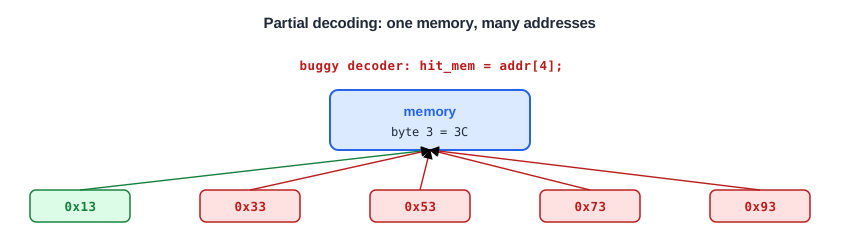
The simulation shows it. The testbench writes 0x3C to memory byte 3 at address 0x13, then reads address 0x53, which the memory map says is unmapped:
75  write addr=13 data=3c    ok
105  read  addr=13 data=3c    ok
135  read  addr=53 data=3c    ok
With the full decoder, the same read returns an error:
125 read addr=53 data=00 ERROR
Aliasing is dangerous in practice. A software bug that writes to a wrong address silently overwrites a real register instead of causing an error, and the cause is very hard to find.
Quick Check
Q: With the partial decoder hit_mem = addr[4], does a write to 0x01 reach the memory?
Show Answer
No: bit 4 of 0x01 is 0. But the register select still checks addr[7:4] == 0, so the write goes to the register slave as intended. Aliasing only adds extra addresses for the memory.
Unmapped Addresses
Every address that no slave owns needs a defined answer. Without one, the master waits forever for a ready that never comes, and the whole system hangs. The usual solution is a default slave, here built into the decoder, that completes the transfer at once with an error. AHB and AXI interconnects include such a default slave, and the error reaches the processor as a bus fault that software can report.
Running It in ChipVerify Lab
The example contains the bus system with the partial decoder and a testbench that reads the unmapped address 0x53. Run it, see the alias, then fix the decoder.
Common Mistakes
Mistake #1: Decoding only some of the upper bits
Partial decoding makes slaves appear at many addresses. Compare all bits above the region size, unless the specification explicitly allows aliasing.
Mistake #2: Overlapping regions
If two regions overlap, two slaves are selected at once and drive the response together. Check that every address maps to at most one slave.
Mistake #3: No default slave
An unmapped access with no answer hangs the master. Always complete it with an error.
Practice Exercise
Challenge: Remove the Alias
Open the example and run it. The read of 0x53 returns memory data. Fix the decoder so the memory only answers at 0x10 to 0x1F, and run again.
Hint
Compare all four upper address bits with the region's base, as the register select already does.
Solution
wire hit_mem = (addr[7:4] == 4'h1);
With the full comparison, the read of 0x53 completes with ERROR and data 00, because no slave owns that address. The accesses to 0x01 and 0x13 are unchanged.
Open the ready-made example in the lab and run the simulation.
Summary
- A memory map gives every slave a range of addresses; power-of-two, naturally aligned ranges keep decoding simple.
- The decoder compares the upper address bits; the lower bits address inside the slave.
- Partial decoding causes aliasing: a slave answers at several addresses, as the read of 0x53 showed.
- Unmapped addresses must complete with an error, from a default slave, or the master hangs.
