
Most APB completers are register blocks: a handful of registers that software uses to configure a peripheral, start it, and read its status. Designing one is mostly about choosing the right behaviour for each register. Some are plain read/write, some are read-only, some clear when software writes a 1, and some drive an interrupt. This article designs a small APB timer peripheral that has all of these and simulates it from programming to interrupt.
9 min read | Intermediate
What You'll Learn
- Plan a register map with access types
- Implement read/write, read-only and write-1-to-clear registers on APB
- Generate a level interrupt from a status bit
- Decide what happens when hardware and software change a bit in the same cycle
The Register Map
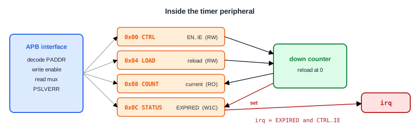
A register block starts on paper. The timer counts down from a reload value and flags each time it reaches zero:
| Offset | Name | Access | Bits |
|---|---|---|---|
| 0x00 | CTRL | Read/write | bit 0 EN: count; bit 1 IE: interrupt enable |
| 0x04 | LOAD | Read/write | Reload value |
| 0x08 | COUNT | Read-only | Current count; a write returns an error |
| 0x0C | STATUS | Write 1 to clear | bit 0 EXPIRED: set when the count reaches zero |
Every other address is unmapped and returns PSLVERR. Unused bits read as zero. Writing this table down before any RTL is worth the effort: the same table feeds the driver code, the documentation, and the register model of a UVM testbench.
Access Types
- Read/write (RW): software writes a value and reads the same value back. CTRL and LOAD.
- Read-only (RO): hardware sets the value, software can only read it. COUNT. A write has no effect; this block also reports an error.
- Write 1 to clear (W1C): hardware sets the bit when an event happens; software clears it by writing 1 to that bit. Writing 0 leaves it alone. STATUS.
Why W1C instead of a plain RW bit? With several event bits in one register, software can clear exactly the events it has handled by writing those bits as 1 and the rest as 0. An event that arrived after software read the register stays set, because software wrote 0 to it. A read-modify-write of a plain RW register would lose it.
Quick Check
Q: STATUS has two W1C bits, both set. Software writes 0b01. What does STATUS read afterwards?
Show Answer
0b10. Writing 1 to bit 0 cleared it; writing 0 to bit 1 left it set.
The RTL
module apb_timer (
  input             PCLK,
  input             PRESETn,
  input             PSEL,
  input             PENABLE,
  input             PWRITE,
  input      [11:0] PADDR,
  input      [31:0] PWDATA,
  output reg [31:0] PRDATA,
  output            PREADY,
  output            PSLVERR,
  output            irq
);
  reg [1:0]  ctrl;
  reg [31:0] load;
  reg [31:0] count;
  reg        expired;

  wire access    = PSEL && PENABLE;
  wire wr        = access && PWRITE;
  wire hit_ctrl  = (PADDR == 12'h000);
  wire hit_load  = (PADDR == 12'h004);
  wire hit_count = (PADDR == 12'h008);
  wire hit_stat  = (PADDR == 12'h00C);
  wire mapped    = hit_ctrl || hit_load || hit_count || hit_stat;
  wire tick_zero = ctrl[0] && (count == 32'd0);   // the counter wraps this cycle

  assign PREADY  = 1'b1;
  assign PSLVERR = access && (!mapped || (hit_count && PWRITE));
  assign irq     = expired && ctrl[1];

  // Software-written registers
  always @(posedge PCLK) begin
    if (!PRESETn) begin
      ctrl <= 2'b00;
      load <= 32'h0;
    end
    else if (wr) begin
      if (hit_ctrl)
        ctrl <= PWDATA[1:0];
      else if (hit_load)
        load <= PWDATA;
    end
  end

  // The counter: reloads while disabled, counts down while enabled
  always @(posedge PCLK) begin
    if (!PRESETn)
      count <= 32'h0;
    else if (!ctrl[0] || tick_zero)
      count <= load;
    else
      count <= count - 32'd1;
  end

  // STATUS.EXPIRED: hardware sets it, software clears it by writing 1.
  // If both happen in the same cycle, the set wins so no event is lost.
  always @(posedge PCLK) begin
    if (!PRESETn)
      expired <= 1'b0;
    else if (tick_zero)
      expired <= 1'b1;
    else if (wr && hit_stat && PWDATA[0])
      expired <= 1'b0;
  end

  always @(*) begin
    case (PADDR)
      12'h000: PRDATA = {30'h0, ctrl};
      12'h004: PRDATA = load;
      12'h008: PRDATA = count;
      12'h00C: PRDATA = {31'h0, expired};
      default: PRDATA = 32'h0;
    endcase
  end
endmodule
Each register gets its own always block with its own rules. The APB part is only the decode wires, the write strobe wr, the read case, and PSLVERR.
When Hardware and Software Collide
EXPIRED can be set by hardware and cleared by software. Sooner or later both happen in the same cycle: the counter reaches zero just as the interrupt handler clears the previous event. One of them has to win. Here the set wins, so the new event survives and the interrupt stays high. If the clear won instead, the event would vanish and software would never know the timer expired again.
Every register that both sides can change needs this decision, and it should be written in the register documentation. "Hardware set has priority over software clear" is the usual answer for event bits.
A Level Interrupt
irq is simply expired && ctrl[1]. It is a level, not a pulse: it stays high until software clears EXPIRED or disables the interrupt. An interrupt controller that samples it later still sees it. A one-cycle pulse is easy to miss if the interrupt controller runs on another clock or is busy.
Keeping the enable separate from the status has a second benefit. Software can poll STATUS with the interrupt disabled, and the event bit still records that the timer expired.
Quick Check
Q: Software clears CTRL.IE while EXPIRED is set, then sets IE again without touching STATUS. What does irq do?
Show Answer
It drops when IE is cleared and rises again when IE is set, because EXPIRED is still 1. The event was not lost, only masked.
The Simulation
The testbench programs the timer like a driver would: set the reload value, enable counting and the interrupt, wait for the interrupt, read and clear the status, then try to write the read-only COUNT.
apb_write(12'h004, 32'd3);           // LOAD = 3
apb_write(12'h000, 32'h3);           // CTRL: EN = 1, IE = 1
apb_read (12'h008, rdata);           // COUNT while it runs
wait (irq);
apb_read (12'h00C, rdata);           // STATUS: EXPIRED = 1
apb_write(12'h000, 32'h2);           // stop the counter, keep IE
apb_write(12'h00C, 32'h1);           // write 1 to clear EXPIRED
apb_read (12'h00C, rdata);
apb_write(12'h008, 32'd99);          // COUNT is read-only: PSLVERR
45  write 0x004 = 0x00000003
75  write 0x000 = 0x00000003
105  read  0x008 = 0x00000001
115  irq rises
145  read  0x00c = 0x00000001
175  write 0x000 = 0x00000002
205  write 0x00c = 0x00000001
205  irq falls
235  read  0x00c = 0x00000000
265  write 0x008 = 0x00000063  PSLVERR
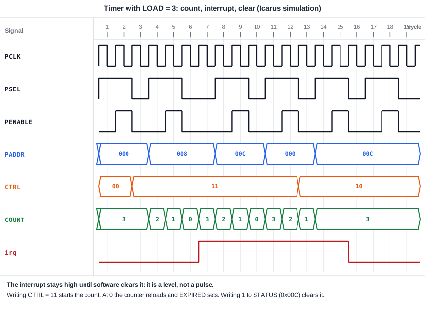
The count runs 3, 2, 1, 0 after the enable, the read at 105 catches it at 1, and irq rises when the counter wraps. The interrupt stays high through the next transfers and falls at the edge where the W1C write completes. The write to COUNT gets PSLVERR.
Running It in ChipVerify Lab
The example contains the timer and the testbench. Run it and follow COUNT, EXPIRED and irq in the waveform.
Common Mistakes
Mistake #1: A W1C bit that clears on any write
Clearing STATUS whenever the register is written, without checking PWDATA[0], breaks the reason for W1C: software can no longer clear one event and keep another.
Mistake #2: Losing an event to a simultaneous clear
If the software clear has priority over the hardware set, an event that arrives in the same cycle disappears. Give the set priority.
Mistake #3: Registers that change when read
A read that clears a status bit or pops a FIFO is tempting but risky: a debugger that dumps all registers changes the state of the chip. Prefer explicit W1C writes, and document any read side effect clearly.
Practice Exercise
Challenge: One-Shot Mode
Add a ONESHOT bit at CTRL[2]. When it is set, the timer clears its own EN bit the first time it reaches zero, so it expires only once. Write a test that sets CTRL to 0b111, waits for the interrupt, and reads CTRL and COUNT.
Hint
Widen ctrl to three bits. The hardware clear of EN goes in the same always block as the software write to CTRL, as an else if after it.
Solution
reg [2:0] ctrl;                          // bit 2: ONESHOT

always @(posedge PCLK) begin
  if (!PRESETn) begin
    ctrl <= 3'b000;
    load <= 32'h0;
  end
  else begin
    if (wr && hit_ctrl)
      ctrl <= PWDATA[2:0];
    else if (tick_zero && ctrl[2])
      ctrl[0] <= 1'b0;                   // one-shot: stop after the first expiry
    if (wr && hit_load)
      load <= PWDATA;
  end
end
// and read CTRL as {29'h0, ctrl}
45  write 0x004 = 0x00000003
75  write 0x000 = 0x00000007
115  irq rises
145  read  0x000 = 0x00000006
175  read  0x008 = 0x00000003
205  read  0x008 = 0x00000003
CTRL reads 0b110: EN cleared itself, IE and ONESHOT stayed. COUNT stays at LOAD because a disabled counter reloads. Note the priority: a software write to CTRL in the same cycle as the expiry wins over the hardware clear, while a write to LOAD does not interfere. Document the choice.
Open the ready-made example in the lab and run the simulation.
Summary
- Start a register block with a register map: offset, name, access type and bit fields.
- Read/write, read-only and write-1-to-clear cover most registers; unused bits read as zero.
- W1C bits let software clear exactly the events it handled.
- When hardware and software change a bit in the same cycle, decide who wins; event bits give the hardware set priority.
- Interrupts are levels built from a status bit and an enable bit.
