
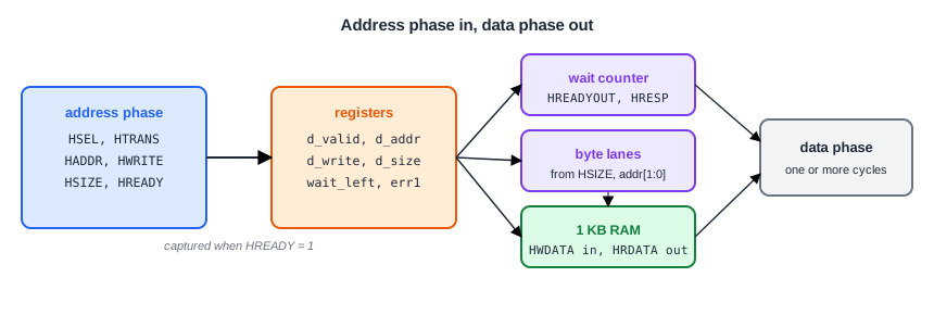
An AHB-Lite slave has one job that is harder than on APB: it must separate the address phase of one transfer from the data phase of another, because both are on the bus in the same cycle. The standard way is to register the address and control at the end of the address phase and use the registered copy in the data phase. This article designs a complete AHB-Lite memory slave that way, with byte, halfword and word transfers, configurable wait states and an ERROR response.
9 min read | Intermediate
What You'll Learn
- Capture the address phase correctly using
HSEL,HTRANSandHREADY - Generate wait states and a two-cycle ERROR with
HREADYOUTandHRESP - Write narrow transfers to the right byte lanes
- Decide which optional AHB signals a slave needs
The Plan
The slave is 1 KB of RAM, the smallest region an AHB slave may own. It supports:
- byte, halfword and word transfers on a 32-bit bus;
- a configurable number of wait states for the first beat of a burst (NONSEQ) and for the following beats (SEQ), with an option to never wait on writes;
- a read-only region at the top, where a write gets an ERROR response.
Ports and Parameters
module ahb_mem #(
  parameter WAIT_NONSEQ = 0,
  parameter WAIT_SEQ    = 0,
  parameter WAIT_WRITES = 1,
  parameter RO_BASE     = 10'h300
) (
  input             HCLK,
  input             HRESETn,
  input             HSEL,
  input      [31:0] HADDR,
  input      [1:0]  HTRANS,
  input             HWRITE,
  input      [2:0]  HSIZE,
  input      [31:0] HWDATA,
  input             HREADY,
  output            HREADYOUT,
  output            HRESP,
  output     [31:0] HRDATA
);
  reg [31:0] mem [0:255];                // 256 words = 1 KB
  integer    i;
The slave has no HBURST, HPROT or HMASTLOCK inputs. A memory does not need the burst type, because each beat carries its own address. The specification recommends that slaves do not use HPROT unless they must, and most slaves have no need for HMASTLOCK because they handle transfers in the order they arrive. A memory controller reached by several masters is the exception.
Capturing the Address Phase
A transfer is accepted at the rising edge where three things are true: HREADY is high (the previous transfer on the bus is finishing), HSEL is high (the transfer is for this slave), and HTRANS is NONSEQ or SEQ. Bit 1 of HTRANS is 1 exactly for those two types, so IDLE and BUSY are ignored:
  // Address phase signals, registered for the data phase
  reg        d_valid;                    // a NONSEQ or SEQ transfer is in its data phase
  reg [9:0]  d_addr;
  reg        d_write;
  reg [2:0]  d_size;
  reg [3:0]  wait_left;                  // wait states still to insert
  reg        err1;                       // first cycle of an ERROR response
  reg        err2;                       // second cycle of an ERROR response

  wire start = HREADY && HSEL && HTRANS[1];        // NONSEQ (10) or SEQ (11) accepted
  wire bad   = start && HWRITE && (HADDR[9:0] >= RO_BASE);

  always @(posedge HCLK) begin
    if (!HRESETn) begin
      d_valid   <= 1'b0;
      wait_left <= 4'd0;
      err1      <= 1'b0;
      err2      <= 1'b0;
    end
    else begin
      err2 <= err1;
      if (err1) begin
        err1    <= 1'b0;                 // second cycle of the ERROR response follows
        d_valid <= 1'b0;
      end
      else if (HREADY) begin
        // A new address phase completes: capture it
        d_valid   <= start && !bad;
        d_addr    <= HADDR[9:0];
        d_write   <= HWRITE;
        d_size    <= HSIZE;
        if (!start || bad || (HWRITE && !WAIT_WRITES))
          wait_left <= 4'd0;
        else if (HTRANS == 2'b10)
          wait_left <= WAIT_NONSEQ;
        else
          wait_left <= WAIT_SEQ;
        err1      <= bad;
      end
      else if (wait_left != 4'd0) begin
        wait_left <= wait_left - 4'd1;
      end
    end
  end
At every edge with HREADY high, the slave copies the address phase into the d_ registers, which describe the transfer now in its data phase. When nothing was accepted, d_valid becomes 0 and the slave answers OKAY with no wait states, which is exactly what the protocol requires for IDLE, BUSY and transfers to other slaves. When HREADY is low, the registers hold, and the wait counter counts down instead.
Quick Check
Q: Why must the capture be qualified with HREADY even though this slave drives its own HREADYOUT?
Show Answer
Because another slave can be holding the bus. In a system with several slaves, HREADY is the HREADYOUT of whichever slave owns the current data phase. If that slave waits, the address phase for this slave is held, and capturing it early would accept it twice, or accept an address the master later changes.
Wait States and ERROR
  // The data phase completes when no wait states are left
  assign HREADYOUT = err1 ? 1'b0 : (wait_left == 4'd0);
  assign HRESP     = err1 || err2;
HREADYOUT stays low while wait states remain, and goes high in the last cycle of the data phase. HRESP stays OKAY during the wait states, as the protocol requires.
A write to the read-only region is caught in the address phase (bad). Instead of starting a data phase, the slave sets err1: the first ERROR cycle, with HREADYOUT low. One cycle later err2 takes over with HREADYOUT high, completing the two-cycle response. The memory is never written, because d_valid stays 0.
Byte Lanes and the Data Phase
  // Byte lanes for the write: little-endian, lane = address bits [1:0]
  wire [3:0] lanes = (d_size == 3'b000) ? (4'b0001 << d_addr[1:0]) :
                     (d_size == 3'b001) ? (d_addr[1] ? 4'b1100 : 4'b0011) :
                                          4'b1111;

  always @(posedge HCLK) begin
    if (d_valid && d_write && HREADYOUT) begin
      if (lanes[0])
        mem[d_addr[9:2]][7:0]   <= HWDATA[7:0];
      if (lanes[1])
        mem[d_addr[9:2]][15:8]  <= HWDATA[15:8];
      if (lanes[2])
        mem[d_addr[9:2]][23:16] <= HWDATA[23:16];
      if (lanes[3])
        mem[d_addr[9:2]][31:24] <= HWDATA[31:24];
    end
  end

  // Read data: the whole word, in the cycle the transfer completes.
  // The master picks the active byte lanes.
  assign HRDATA = (d_valid && !d_write && HREADYOUT) ? mem[d_addr[9:2]] : 32'h0;
endmodule
The lane logic follows the little-endian byte-lane rule. A byte uses the lane given by address bits 1:0; a halfword uses lanes 1:0 or 3:2 depending on address bit 1; a word uses all four. Only the active lanes are written, so a byte write leaves the other three bytes of the word alone.
The write happens at the edge where the data phase completes (HREADYOUT high), so HWDATA, which the master held through any wait states, is sampled exactly once. For reads, the slave returns the whole word and the master picks out its lanes. HRDATA is only driven in the completing cycle; during wait states its value does not matter.
Quick Check
Q: Which byte lanes does a halfword write to address 0x106 enable, and which bytes of the word at 0x104 change?
Show Answer
Address bit 1 is set, so lanes 3 and 2 (HWDATA[31:16]). Bytes 0x106 and 0x107 change; bytes 0x104 and 0x105 keep their values.
The Simulation
The testbench writes a word, then a halfword and a byte into the same word, reads it back, runs an INCR4 write and read, and finally writes to the read-only region. The slave has one wait state on the first beat of each burst:
burst(1, SINGLE, 32'h010, WORD, 1, 32'h11223344);   // a word
burst(1, SINGLE, 32'h012, HALF, 1, 32'hBEEF);       // upper halfword of that word
burst(1, SINGLE, 32'h011, BYTE, 1, 32'h5A);         // byte 1 of that word
burst(0, SINGLE, 32'h010, WORD, 1, 0);
burst(1, INCR4,  32'h100, WORD, 4, 32'h40);
burst(0, INCR4,  32'h100, WORD, 4, 0);
burst(1, SINGLE, 32'h300, WORD, 1, 32'hBAD);        // read-only region: ERROR
45  write 0x0010 = 0x11223344  OKAY
65  write 0x0012 = 0xbeef0000  OKAY
85  write 0x0011 = 0x00005a00  OKAY
105  read  0x0010 = 0xbeef5a44  OKAY
125  write 0x0100 = 0x00000040  OKAY
135  write 0x0104 = 0x00000041  OKAY
145  write 0x0108 = 0x00000042  OKAY
155  write 0x010c = 0x00000043  OKAY
175  read  0x0100 = 0x00000040  OKAY
185  read  0x0104 = 0x00000041  OKAY
195  read  0x0108 = 0x00000042  OKAY
205  read  0x010c = 0x00000043  OKAY
225  write 0x0300 = 0x00000bad  ERROR
The word at 0x10 reads back as 0xBEEF5A44: the halfword replaced bytes 3 and 2, the byte replaced byte 1, and byte 0 kept its original 0x44. The singles each pay one wait state, while each INCR4 pays it only on its first beat.
Running It in ChipVerify Lab
The example contains this slave and the testbench. Change WAIT_SEQ to 1 and watch the burst slow down.
Common Mistakes
Mistake #1: Writing memory in the address phase
At the address-phase edge, HWDATA still belongs to the previous transfer. Register the address and write in the data phase.
Mistake #2: Treating BUSY as a transfer
Capturing whenever HTRANS is not IDLE counts BUSY cycles as beats. Use HTRANS[1], which is high only for NONSEQ and SEQ.
Mistake #3: Writing all four lanes for a narrow write
A byte or halfword write must change only its own bytes. Writing the whole word copies whatever the master left on the inactive lanes into memory.
Practice Exercise
Challenge: Reject Unaligned Transfers
A correct master never issues an unaligned transfer, but a robust slave can reject one. Make the slave answer ERROR to a halfword at an odd address or a word at an address that is not a multiple of 4. Then add a halfword write to 0x011 to the testbench.
Hint
Add the unaligned condition to bad, so it uses the same two-cycle ERROR path as the read-only region.
Solution
wire unaligned = (HSIZE == 3'b001 && HADDR[0]) || (HSIZE == 3'b010 && HADDR[1:0] != 2'b00);
wire bad       = start && ((HWRITE && (HADDR[9:0] >= RO_BASE)) || unaligned);
45  write 0x0010 = 0x11223344  OKAY
65  write 0x0012 = 0xbeef0000  OKAY
85  write 0x0011 = 0x00005a00  OKAY
105  write 0x0011 = 0x00777700  ERROR
125  read  0x0010 = 0xbeef5a44  OKAY
The unaligned halfword fails and leaves memory untouched: the word still reads 0xBEEF5A44. The rest of the log is the same, 20 ns later.
Open the ready-made example in the lab and run the simulation.
Summary
- Register the address phase at every edge where
HREADYis high; accept a transfer only whenHSELis high andHTRANSis NONSEQ or SEQ. - Use the registered copy in the data phase: write memory and drive read data there.
- Drive
HREADYOUTlow for wait states withHRESPOKAY; give ERROR as two cycles. - Write only the byte lanes selected by
HSIZEand the low address bits. - Most slaves can ignore
HBURST,HPROTandHMASTLOCK.
