
Synthesis doesn't just produce a text log — it produces a schematic you can actually explore. This article covers the basics: opening it, moving around, and correlating it back to the netlist and source code.
6 min read | Beginner Level
What You'll Learn
- How to open and navigate the schematic panel
- How to click a net to highlight it
- How cross-probing links the schematic back to your RTL in the editor
Opening the Schematic Panel
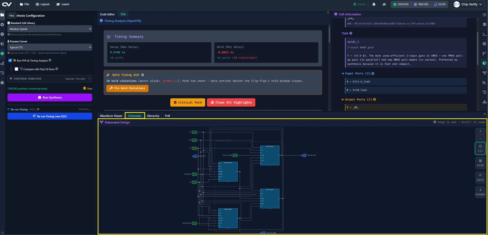
After a successful synthesis run, open the Schematic panel. You'll see the top-level view of shift_register_4bit: four shift_reg_bit instances wired in a chain, matching the structure you wrote in Chapter 1.
Pan & Zoom
Drag anywhere on the canvas to pan, and use the mouse wheel (or the +/− buttons) to zoom in and out. The schematic auto-fits to the view whenever it first loads or you navigate hierarchy, but if you've panned or zoomed away from that and want back, click Fit to snap back to a full view of the current level — useful once you're navigating a design too large to eyeball your way back.
Clicking a Net to Highlight It
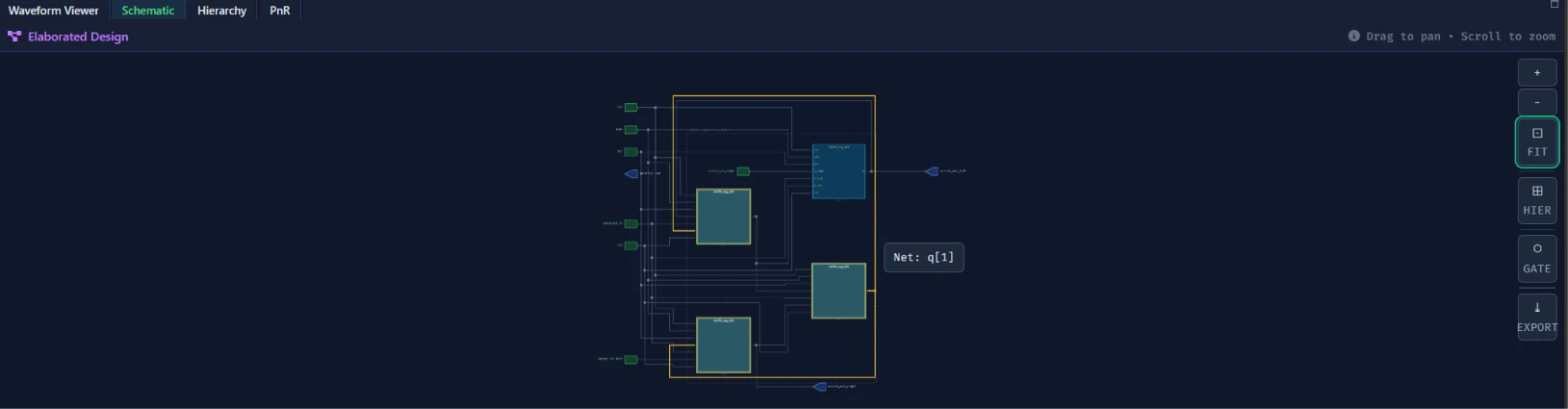
Click any wire in the schematic and it highlights, making it easy to trace a single signal — for example q[1], which connects bit1's output to d_right input of bit0.
Cross-Probing Between the Editor and Schematic
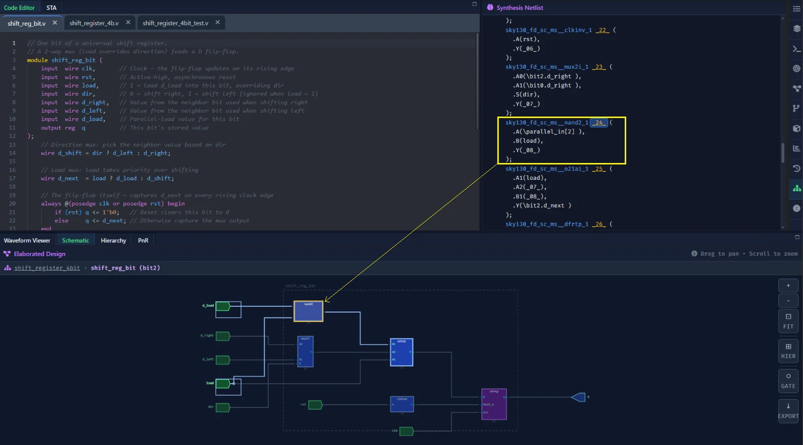
Cross-probing works both directions. Click a cell in the schematic and the netlist panel scrolls to and highlights the corresponding line. Select the cell in the netlist panel instead, and the matching cell highlights in the schematic.
Common Mistakes
Mistake #1: Expecting the schematic to auto-update after an RTL edit
The schematic reflects the last successful synthesis run, not your current editor content. Edit the RTL, then re-run synthesis, before expecting the schematic to change.
Mistake #2: Clicking a bus and being surprised multiple wires highlight
Clicking a multi-bit net (like parallel_out[3:0] at the top level) highlights every bit of the bus at once — that's expected, not a rendering glitch.
Where Is This Used?
Schematic cross-probing is how engineers debug real, much larger netlists — jumping from "this gate looks wrong" straight to the line of RTL that produced it is dramatically faster than reading raw structural Verilog by eye.
Practice Exercise
Challenge: Trace a Serial Input
Find and click the net carrying serial_in_left in the schematic, and confirm it leads into bit0 — matching the wiring from Chapter 1's shift_register_4bit.v.
Hint
Look at the left edge of the schematic for the design's top-level input ports.
Solution
serial_in_left connects directly to bit0's d_left input — the instance declaration shift_reg_bit bit0 (..., .d_left(serial_in_left), ...) is exactly what the schematic is drawing.
Summary
In this tutorial, you learned:
- How to open the schematic after synthesis
- How to pan and zoom around it
- How to click a net to highlight it
- How cross-probing links the schematic and the editor in both directions
