
In simulation, every register starts as X and a testbench applies a reset before anything else. A formal tool starts differently: every register may hold any value in the first cycle, and the reset is just another input that can be high or low in any cycle. This article explains how a formal run starts, why a reset assumption is needed, why initial values in the RTL can mislead you, and how a missing reset on one register shows up as a counterexample.
9 min read | Beginner to Intermediate
What You'll Learn
- Describe the start state of a formal run and how the reset assumption shapes it
- Explain how formal treats registers without a reset and registers with an initial value
- Find a register that is missing from the reset with a property
- Explain why the reset should stay free after the first cycle
Any Value in the First Cycle
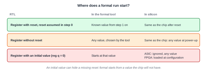
A formal tool does not know what the flip-flops of a chip contain when the power comes on, and neither does anybody else. So in step 0 every register is free: the tool may choose any value for it, just as it chooses inputs. Properties that hold only from a clean state would fail at once.
The fix is the reset assumption you have used in every example so far:
initial m_rst: assume (rst); // SVA: reset in the first cycle
In the lab form it is the init register and if (init) assume (rst);, or initial assume (rst == 1'b1); as in the lab template. After the reset cycle, every register that the reset clears has its reset value, and the check starts from the same state as a real chip after reset.
Registers Without a Reset
Not every register needs a reset. Data registers in a pipeline usually have none, because their content is only used when a valid bit says so, and leaving out the reset saves area and power. In formal, such a register keeps an arbitrary value after the reset cycle, exactly as in silicon. That is correct, and the properties must cope with it: a data register without a reset can hold anything until the first valid word arrives.
The danger is a control register that should be reset and is not. Then the arbitrary value leaks into the behavior after reset, and the formal tool finds it, because it is free to choose the worst start value.
Quick Check
Q: After the reset cycle, a data register without a reset holds 8'hA5 in the counterexample. Is that a bug?
Show Answer
Not by itself. A register without a reset may hold any value until it is written. It is a bug only if that value is used, for example if it reaches an output while the output is marked valid.
The Design: a Valid Pipeline With a Missing Reset
This two-stage pipeline carries a data word and a valid bit. The data registers have no reset, which is fine. But the designer reset only the first valid bit:
module valid_pipe (input clk, input rst, input in_valid, input [7:0] in_data,
                   output out_valid, output [7:0] out_data);
  reg       v1, v2;
  reg [7:0] d1, d2;
  always @(posedge clk) begin
    if (rst) v1 <= 1'b0;                       // bug: v2 is not reset
    else     v1 <= in_valid;
    v2 <= v1;
    d1 <= in_data;
    d2 <= d1;
  end
  assign out_valid = v2;
  assign out_data  = d2;
endmodule
Two rules: every valid output word entered two cycles earlier, and nothing comes out in the cycle after a reset.
a_from_input: assert property (@(posedge clk) disable iff (rst) out_valid |-> $past(in_valid, 2));
a_after_rst:  assert property (@(posedge clk) $fell(rst) |-> !out_valid);
Running It in ChipVerify Lab
`ifdef FORMAL
  reg init = 1'b1;
  always @(posedge clk) init <= 1'b0;
  always @(*) if (init) assume (rst);
  // an output word is always one that came in two cycles earlier
  always @(posedge clk)
    if (!init && !$past(rst) && !$past(rst, 2) && out_valid) assert ($past(in_valid, 2));
  // no output in the cycle after reset
  always @(posedge clk) if (!init && $past(rst)) assert (!out_valid);
`endif
The run fails at step 2:
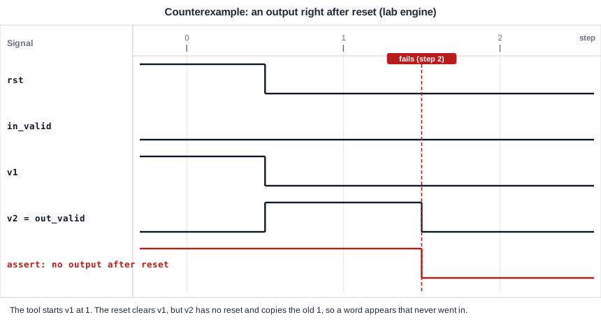
The tool started v1 at 1. The reset in step 0 clears v1, but v2 copies the old value of v1 at the same clock edge, so out_valid is high in step 1. A word that never went in comes out of the pipeline right after reset, carrying whatever the data registers held. Add v2 to the reset and the run passes.
Initial Values Can Hide a Missing Reset
Verilog allows an initial value in a declaration, such as reg v2 = 1'b0;. The formal tool honors it: the register starts at that value instead of an arbitrary one. FPGAs honor it too, because the configuration loads every flip-flop. An ASIC does not. Its flip-flops come up with unknown values, and synthesis for ASICs ignores initial values.
So an initial value can make a formal check pass on a design that fails in silicon. A counter without a reset and with initial q = 0 passes a range check, while the same counter without the initial value fails in step 1, starting from 14. For ASIC designs, keep initial values out of the RTL, or make sure the formal setup does not rely on them.
Keep the Reset Free After the First Cycle
The reset assumption only forces the reset in the first cycle. After that, rst is a free input like any other, and the tool may raise it at any time. This is deliberate. A real chip can be reset in the middle of operation, by a watchdog or by software, and the design must recover cleanly from a reset in any state, not just from power-up.
The exercise shows a bug that only a reset in the middle of traffic reveals.
Quick Check
Q: Why not assume the reset is low after the first cycle, to keep the traces simpler?
Show Answer
Because the design must handle a reset at any time. Forbidding later resets removes every sequence with a mid-operation reset, and reset bugs that only show up in a busy state are never found.
Common Mistakes
Mistake #1: Running without a reset assumption
Without it, the tool starts every register at its worst value and reports failures from states the chip never reaches after reset. Assume the reset in the first cycle.
Mistake #2: Using initial values as a substitute for reset
Formal and FPGA flows honor initial values, ASIC silicon does not, and a reset in the middle of operation ignores them anyway. A control register that must start clean needs a reset.
Mistake #3: Forbidding the reset after the first cycle
An assumption such as "rst is low after step 0" hides every bug that appears when the design is reset in a busy state. Leave the reset free.
Practice Exercise
Challenge: Initial Values Are Not a Fix
Open the example and run it. Instead of adding v2 to the reset, try a shortcut: give both valid bits an initial value, reg v1 = 1'b0; and reg v2 = 1'b0;. Run again. Does the check pass? Read the counterexample and explain it.
Hint
Look at the reset input in the counterexample. Is it only high in step 0?
Solution
The check still fails, now at step 4. The tool sends a valid word in step 1, so v1 is 1 in step 2, and raises the reset in step 2. The reset clears v1 but not v2, which copies the 1 and shows a valid output in step 3, the cycle after the reset. The initial values only help at power-up. The real fix is to reset v2:
if (rst) begin v1 <= 1'b0; v2 <= 1'b0; end
else     begin v1 <= in_valid; v2 <= v1; end
With it the run passes, with or without initial values.
Open the ready-made example in the lab and run the formal check from the formal panel. The free tier allows a depth of up to 10 cycles, and PRO allows up to 100.
Summary
- In step 0 of a formal run, every register may hold any value. A reset assumption in the first cycle gives the clean start of a real chip.
- Registers without a reset stay arbitrary after reset, in formal and in silicon. That is fine for data, and a bug for control.
- A valid bit missing from the reset was found at step 2: a word came out of the pipeline right after reset.
- Initial values in the RTL are honored by formal tools and FPGAs but not by ASICs, so they can hide a missing reset.
- Keep the reset free after the first cycle, so that resets in the middle of operation are checked too.
