
The last capstone checks a UART transmitter, the same kind of block whose timing the Static Timing Analysis capstone analyzes. Where STA asks whether the gates are fast enough, formal asks whether the logic sends the right frame: a start bit, the data bits in the right order, a stop bit, each for the right number of clock cycles. The design is parameterized so that the check fits the free lab depth, and the full-size version runs with PRO.
11 min read | Intermediate
What You'll Learn
- Turn a serial protocol frame into properties with a reference timeline
- Check every data bit with a symbolic bit index
- Find a bit-order bug in a transmitter
- Scale the check from a small frame to the full UART frame
The Frame
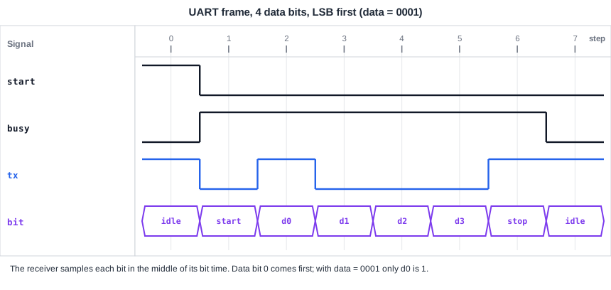
A UART line is high when idle. A frame starts with a start bit of 0, then sends the data bits, least significant first, then a stop bit of 1. Each bit lasts a fixed number of clock cycles, set by the baud rate. The transmitter here has two parameters: N data bits and BAUD clock cycles per bit. A real UART uses 8 data bits and a BAUD of tens or hundreds; the check uses small values.
The Design
module uart_tx #(parameter N = 4, parameter BAUD = 1) (input clk, input rst, input start, input [N-1:0] data,
                                                 output reg tx, output busy);
  reg [N-1:0] sh;
  reg [4:0]   bitn;          // 0 = start bit, 1..N = data bits, N+1 = stop bit
  reg [7:0]   cnt;           // clocks left in the current bit
  reg         active;
  assign busy = active;
  always @(posedge clk)
    if (rst) begin
      active <= 1'b0; tx <= 1'b1;
    end else if (!active) begin
      tx <= 1'b1;
      if (start) begin active <= 1'b1; sh <= data; bitn <= 5'd0; cnt <= BAUD - 1; tx <= 1'b0; end
    end else if (cnt != 0) begin
      cnt <= cnt - 8'd1;
    end else begin
      cnt <= BAUD - 1;
      bitn <= bitn + 5'd1;
      if (bitn < N)       begin tx <= sh[N-1]; sh <= sh << 1; end   // bug: sends MSB first, the spec says LSB first
      else if (bitn == N) tx <= 1'b1;                               // stop bit
      else                begin active <= 1'b0; tx <= 1'b1; end
    end
endmodule
The shift register sends the most significant bit first. Many serial protocols do, such as SPI and I2C, which makes this an easy mistake when code is reused; UART sends the least significant bit first.
The Properties
A reference timeline t counts clock cycles from the start of the frame, and ref_d remembers the data. A symbolic bit index k, as in the symbolic values article, checks every data bit with one assertion:
`ifdef FORMAL
  // ... reset assumption ...
  // the line is high whenever the transmitter is idle
  always @(*) if (!init && !busy) assert (tx == 1'b1);
  // reference model: count clocks since the start of the frame, and remember the data
  reg [7:0] t = 8'd0; reg [N-1:0] ref_d; reg on = 1'b0;
  always @(posedge clk)
    if (rst) on <= 1'b0;
    else if (!busy && start) begin on <= 1'b1; t <= 8'd0; ref_d <= data; end
    else if (on) begin t <= t + 8'd1; if (!busy) on <= 1'b0; end
  // a symbolic data bit index: the tool picks which bit to check
  (* anyconst *) reg [4:0] k;
  always @(*) assume (k < N);
  // start bit, data bit k, stop bit, each held for BAUD cycles
  always @(*) if (!init && on && busy && t < BAUD) assert (tx == 1'b0);
  always @(*) if (!init && on && busy && t >= BAUD * (k + 1) && t < BAUD * (k + 2)) assert (tx == ref_d[k]);
  always @(*) if (!init && on && busy && t >= BAUD * (N + 1) && t < BAUD * (N + 2)) assert (tx == 1'b1);
  // the frame takes exactly N + 2 bit times
  always @(posedge clk) if (!init && on && $past(busy) && !busy) assert (t == BAUD * (N + 2));
`endif
In SVA, the data-bit rule is a sequence: after the start, ##(BAUD * (k + 1)) cycles, tx equals data bit k for BAUD cycles. The reference timeline is the lab form of that sequence.
The Counterexample
With N = 4 and BAUD = 1, the run fails at step 3. The tool starts a frame in step 1 with data = 1, so only bit 0 is set, and checks k = 0. The start bit appears in step 2, as it should. In step 3, bit 0 should be on the line, a 1, but the transmitter sends bit 3, a 0. Change the shift to tx <= sh[0]; sh <= sh >> 1; and every check passes.
Quick Check
Q: Why did the tool choose data = 1 and k = 0?
Show Answer
That is one of the shortest ways to make the first data bit wrong: with only bit 0 set, LSB-first sends a 1 and MSB-first sends a 0. Any data whose bit 0 differs from bit 3 would do; the solver picks one.
Scaling Up
The fixed transmitter passes on the lab engine for:
| N | BAUD | Depth | Result |
|---|---|---|---|
| 4 | 1 | 10 | pass, under a second |
| 4 | 2 | 16 | pass, under a second |
| 8 | 1 | 14 | pass, under a second |
| 8 | 4 | 50 | pass, about 2 seconds |
The last row is a full 8-bit frame with 4 cycles per bit, 40 cycles long. A meant-to-fail check that a frame never completes fails at step 9 for N = 4, BAUD = 1, which shows that the depth of 10 really covers a whole frame. For a real baud divider of, say, 434 clocks per bit, the timing logic is the same code with a larger parameter; prove it with the small values and check the divider separately.
Quick Check
Q: What depth does a full frame need for N = 8 and BAUD = 4?
Show Answer
The frame is 10 bit times of 4 cycles, 40 cycles, plus the reset, the start request and the reporting step: a little over 40. The table uses 50.
Running It in ChipVerify Lab
The example is the buggy transmitter with N = 4 and BAUD = 1, which fits the free depth. With PRO, raise the parameters and the depth as in the table.
Common Mistakes
Mistake #1: Checking only "the frame starts and ends"
Start and stop bits can be perfect while the data is reversed. Check every data bit, which the symbolic index does with one assertion.
Mistake #2: Running the real baud rate
Hundreds of cycles per bit make the frame thousands of cycles long. Use a small BAUD for the frame logic and check the divider on its own.
Mistake #3: Forgetting the idle line
A transmitter that drives the line low between frames would look like a start bit to the receiver. "The line is high when idle" is a one-line property; include it.
Practice Exercise
Challenge: Fix the Bit Order and Scale Up
Open the example and run it. Fix the bit order. Then run with N = 8 and, with PRO, with BAUD = 4 at depth 50. Finally add a meant-to-fail check that a frame completes, and note the step.
Hint
LSB first means sending sh[0] and shifting right.
Solution
The fix is if (bitn < N) begin tx <= sh[0]; sh <= sh >> 1; end. All checks pass for the sizes in the table. The meant-to-fail check always @(posedge clk) if (!init) assert (!(on && $past(busy) && !busy)); fails at step 9 for N = 4, BAUD = 1: a frame requested in step 1 ends 6 bit times later.
Open the ready-made example in the lab and run the formal check from the formal panel. The free tier allows a depth of up to 10 cycles, and PRO allows up to 100.
Summary
- A serial frame becomes properties with a reference timeline and a symbolic bit index.
- A transmitter that sent the MSB first failed at step 3 with a one-bit data word.
- The fixed transmitter passed from 4 data bits at one clock per bit up to a full 8-bit frame at 4 clocks per bit.
- Use small parameters for the frame logic; check the baud divider separately.
