
An SoC netlist has thousands of wires connecting blocks together. Every reset line, every clock, every data bus, every control signal has to land on the right pin of the right block. That's a different question from a connectivity matrix check. A connectivity matrix check proves a legal transaction actually gets from a master to a slave. A connectivity verification check proves the wire itself is soldered to the right place - independent of whether any transaction ever runs on it.
10 min read | Intermediate Level
What You'll Learn
- Why connectivity bugs are a different class of bug than the functional bugs simulation is built to catch
- Why simulation struggles to prove a wire is connected, even when it can prove a transaction succeeds
- What a formal connectivity check actually proves, and how it differs from a regular formal property proof
- The four categories of connectivity a formal tool typically checks: point-to-point, reset, clock, and DFT
- Why connectivity apps can run on a whole chip when general-purpose formal usually can't
Why Connectivity Bugs Are a Different Class of Bug
A connectivity bug isn't a logic bug. The block on each end of a wire can be perfectly correct, and the wire between them can still go to the wrong place. A common cause is integration: a top-level netlist stitching together hundreds of module instances, each with dozens of ports, generated or hand-connected by name.
A single swapped port, a mux select tied to the wrong constant, or a bus connected one bit off from where it should be - and everything downstream of that wire behaves exactly as designed, just on the wrong data.
These bugs are common because the sheer number of connections makes them common. A single subsystem can have thousands of point-to-point connections. A full SoC can have over a million. At that scale, a typo-class error isn't an edge case - it's a near-certainty somewhere in the design, and the job is finding it before tapeout, not hoping it isn't there.
Why Simulation Struggles to Prove a Wire Is Connected
Simulation proves a wire is connected by driving a value on one end and observing it arrive at the other. That works, but only for the exact scenario the test happened to create. Getting a specific mux select into the state that routes through a specific input takes a directed test, and there can be thousands of such states to cover, each needing its own test to set up.
There's a subtler problem too. Two signals toggling together in a waveform doesn't prove they're connected - it might just mean two unrelated signals happened to change at the same time in that one test. Confirming an actual causal connection, not a coincidence, needs a test built specifically to distinguish the two, for every wire, in every mode the design can be in.
The bugs this misses aren't always harmless. A connectivity bug at SoC level can sit quietly for many cycles before it produces an observable effect somewhere completely unrelated to where the wire actually broke - which is exactly the kind of failure that's brutal to root-cause once it does show up.
What Formal Proves Instead
A formal connectivity check doesn't run a scenario - it considers every possible value the relevant signals could take, all at once, and proves the connection holds for all of them, or returns a counterexample showing exactly where it doesn't. That's the same exhaustive guarantee formal always offers, applied to a much narrower, much more mechanical question: does this specific output always equal this specific input, under this specific condition.
Most formal connectivity tools - Cadence's JasperGold Connectivity App, Synopsys's VC Formal Connectivity App, and Siemens Questa's equivalent are the common ones in industry use - don't ask an engineer to hand-write that property for every wire. They take a connectivity intent, usually described as a spreadsheet-style table of source, destination, and condition, and generate the assertions automatically:
| Source | Destination | Condition |
|---|---|---|
| mux_sel == 2'b01 | dest_sig | src_a |
| mux_sel == 2'b10 | dest_sig | src_b |
| por_rst_n | block_x.rst_n | (always) |
A generated assertion for the first row looks roughly like this, and formal proves it holds for every reachable value of every other signal in the design, not just the ones a directed test happened to set up:
assert property (@(posedge clk)
  (mux_sel == 2'b01) |-> (dest_sig == src_a));
The Four Kinds of Connectivity a Formal Check Covers
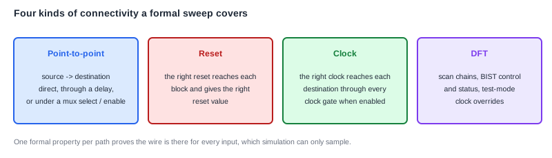
Connectivity checks group into a few recurring categories, and a thorough sweep covers all of them, not just the obvious data-path wires:
Point-to-point. The direct case: source connects to destination, sometimes through a fixed delay, sometimes only under a condition like a mux select or an enable - the table above covers all three variants.
Reset connectivity. Every block needs to see the right reset signal and land in the right reset value. This gets genuinely hard to track by hand once a chip has multiple power domains and more than one reset source feeding different parts of the design.
Clock connectivity. The right clock waveform has to reach every destination when that clock path is enabled, through however many clock gates sit between the source and the block. Checking every gating condition by simulation is expensive; checking it by formal proof is one property per path.
DFT connectivity. Scan chains, BIST control and status signals, and the logic that overrides mission-mode clocking when the chip is in test mode - all rarely exercised by functional tests, and all still need to be wired correctly for the chip to be testable in the factory.
How Connectivity Apps Scale to the Whole Chip
General-purpose formal struggles at full-chip scale, because proving an arbitrary property has to reason about state anywhere in the design that could affect it, and full-chip state space is enormous. A connectivity check sidesteps that problem almost entirely.
Proving one wire's connectivity only depends on the logic actually sitting between that source and that destination - a mux, a gate, maybe a small decoder. Everything else in the chip gets trimmed away before the proof even starts, because it's provably irrelevant to that one question.
That's what lets connectivity apps run properties across an entire SoC, including chips with tens of thousands of module instances, in runs that complete in hours rather than needing the design broken into hand-sized formal-friendly chunks.
One reported industry project ran roughly 3,500 automatically generated connectivity properties on a subsystem and found about 100 bugs on the first pass, ranging from simple miswiring to interface mismatches - the kind of count that makes clear how unlikely it is that simulation regression would have stumbled onto all of them by accident.
What Formal Still Leaves for Simulation
A connectivity proof answers one question: is the wire connected the way the spec says. It says nothing about whether the block on the far end does anything useful with what arrives on that wire, or whether the transaction that travels down it gets the right response back, survives a protocol bridge intact, or gets blocked by a security check when it should.
That functional behavior is still simulation's job - proving each master-slave transaction actually works end to end, the way a connectivity matrix check does. The two techniques aren't competing - a chip needs both a proof that every wire goes where it should, and tests that prove the traffic flowing over those wires behaves correctly.
Common Mistakes
Mistake: Trying to catch connectivity bugs with directed simulation tests instead of a formal connectivity sweep.
A handful of directed tests can catch a handful of miswired signals. They can't cover thousands of point-to-point connections, every mux state, and every reset and clock path across a whole chip - that's the scale formal connectivity checking exists to handle.
Mistake: Treating "the signals toggled together" as proof of a real connection.
Correlated toggling in one simulation trace can happen by coincidence. A formal proof, or a test built specifically to force the values apart, is what actually confirms a causal connection rather than an accidental one.
Mistake: Skipping DFT and reset connectivity because they don't show up in functional test failures.
A broken scan chain or a reset signal wired to the wrong domain often produces no functional simulation failure at all - it just makes the chip untestable or unreliable in silicon, discovered far too late to fix cheaply.
Summary
In this article, you learned:
- Connectivity bugs are integration bugs, not logic bugs - both ends of a wire can be correct while the wire itself goes to the wrong place
- Simulation struggles to prove connectivity exhaustively, since it needs a directed scenario per connection and can't easily tell a real connection from a coincidence
- Formal connectivity checks prove a connection holds for every possible value, generated automatically from a spreadsheet-style table of source, destination, and condition
- The four recurring categories are point-to-point, reset, clock, and DFT connectivity - all common sources of integration bugs that are easy to miss functionally
- Connectivity apps scale to full-chip size because each proof only needs the small slice of logic between one source and one destination, unlike general-purpose formal properties
- Formal proves the wiring is correct; simulation still has to prove the traffic that flows over those wires behaves correctly - the two techniques cover different halves of the same problem
