
Power domains create almost exactly the same category of problem as clock and reset domains, just with a different failure mode. Instead of metastability, a boundary between a powered-down block and an active one produces an undefined value - an X - and instead of a synchronizer, the fix is a piece of dedicated structural logic that has to be present, correctly configured, and correctly sequenced at exactly the right moment. Getting any of that wrong doesn't just cost performance or battery life; it corrupts real data.
13 min read | Intermediate Level
What You'll Learn
- Why powering down part of a chip creates the same kind of cross-domain problem as clock and reset domains
- The four structural elements power-aware verification checks for at every domain boundary
- How X-propagation makes a missing isolation cell dangerous, and why waiting for it to reach a scoreboard is too slow
- What power sequencing verification actually checks beyond "did the domain turn off"
Why Power Domains Are Another Domain-Crossing Problem
An SoC built for low power splits its logic into multiple power domains - some blocks stay always-on, others get power-gated off entirely when idle to save leakage, and some run at a lower voltage to save dynamic power. Just like clock and reset domains, these boundaries don't exist inside any single IP block's own testbench; they're created when blocks are assembled into a chip and wired to a shared power management scheme. A signal that crosses from a domain that might be powered off into one that's always on needs the same kind of dedicated protection a clock crossing needs, just built from different structural cells.
The Four Structural Elements Power-Aware Verification Checks
Power-aware verification is largely about confirming four specific kinds of cells exist everywhere they're required, and that each one does its job correctly:
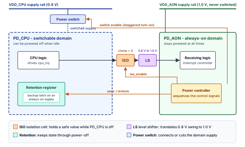
- Isolation cells sit on any signal driven by a domain that can power off, feeding a domain that stays on. When the driving domain is off, the isolation cell clamps its output to a safe, predefined value instead of passing through whatever the now-unpowered logic happens to be producing.
- Level shifters sit between domains running at different voltages, translating a signal from one voltage swing to another so the receiving domain doesn't see an invalid logic level.
- Retention registers hold their value through a power-down event using a small always-on backup cell, so a domain can power off and later power back on without losing state software needs to resume correctly.
- Power switches are the actual gates that connect or disconnect a domain from its supply rail, usually turned on in a staggered sequence to avoid a sudden current surge across the whole chip.
The diagram below shows all four at one boundary: a switchable CPU domain at 0.8 V driving an interrupt line into an always-on domain at 1.0 V. The crossing needs both an isolation cell and a level shifter, and a power controller in the always-on domain drives every control signal.
Every one of these can fail in essentially the same two ways: it can be missing where the design needs it, or it can be present but misconfigured - the wrong clamp value, the wrong direction, a retention register that doesn't actually get restored. Both failure modes look identical from the outside until the specific corner case that exposes them actually runs.
What Actually Gets Checked, Per Element
"Check the isolation cells" isn't specific enough to write a test plan from. Each structural element breaks down into concrete pass/fail conditions, and each one is checked by a different combination of static, dynamic, and formal methods:
- Isolation: is a cell present at every boundary where a switchable domain feeds an always-on one (a static, structural question - answered by comparing the UPF description against the actual netlist, not by simulation), does the clamp drive the correct constant value the receiving logic expects, and is the isolation enable asserted with the correct polarity at the correct point in the sequence (a dynamic question - answered by power-aware simulation and the kind of targeted assertion shown in the next section).
- Level shifters: is one present at every crossing between two supply sets running at different voltages, and does it shift in the correct direction - low-to-high or high-to-low aren't interchangeable, and a shifter built for the wrong direction can pass a quick sanity check while still being structurally wrong.
- Retention: does the retained value actually get saved before the domain loses power, and - separately - does the restored value after power-up match what was saved, bit for bit. These are two distinct checks; a retention cell can save correctly and still restore incorrectly, and a test that only looks at the final restored value can miss a save that happened at the wrong time.
- Power switches: do they turn on in the defined staggered order rather than all at once, since simultaneous switching across a large domain can draw enough inrush current to cause a voltage droop elsewhere on the chip - a system-level side effect a single-domain testbench won't see at all.
X-Propagation: What Happens When Isolation Is Missing
Power-aware simulation models a powered-down domain's outputs as X - unknown - rather than a stable 0 or 1, because that's genuinely what unpowered logic produces. If isolation is missing, misconfigured, or simply not enabled at the right moment, that X flows straight into the active domain, and from there into anything that reads it. A single X value can spread to thousands of downstream signals within a few clock cycles, turning one small structural bug into a simulation full of unrelated-looking corruption.
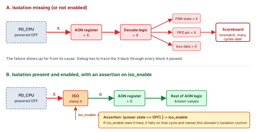
The naive way to catch this is to let the X propagate until it reaches a scoreboard and produces a visibly wrong result - but by then the X has already spread so widely that root-causing it back to the one missing isolation cell is slow and painful. The better approach is targeted assertions that watch the isolation and retention control signals directly: the moment a domain's power state says "off" and its isolation enable isn't actually asserted, that's a violation worth flagging immediately, at the exact cell responsible, rather than waiting to see what eventually breaks downstream.
The assertion below ties domain_power_state to iso_enable for one domain:
// Checks that isolation is actually enabled whenever this domain
// is in its OFF power state - fires immediately, not after the
// resulting X has already propagated elsewhere
property isolation_enabled_when_off;
  @(posedge clk)
  (domain_power_state == PSTATE_OFF) |-> iso_enable;
endproperty

assert property (isolation_enabled_when_off)
  else `uvm_error("PWR_ISO", "Domain is OFF but isolation is not enabled")
Sample clk from an always-on clock. The domain's own clock is gated off before power-down, so an assertion clocked by it would stop evaluating exactly when the check matters.
Power Sequencing: More Than "Did It Turn Off"
A domain's power-down and power-up aren't single events - they're an ordered sequence, each step with real timing requirements between it and the next. A common power-down order is: stop the domain clock, enable isolation, save state into retention, then cut power. Power-up runs the other way: restore power and wait for the supply to settle, restore state from retention, release isolation, then restart the clock. The exact order and delays are design-specific and set by the power controller, but a few rules hold almost everywhere: isolation must be on before power drops, the supply must be stable before restore, and isolation must not be released until restore has completed.
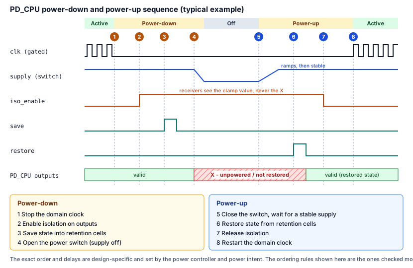
Getting that order wrong - releasing isolation before retention has actually restored state, for instance - produces exactly the same kind of corrupted-data bug as a reset sequencing error, just triggered by a power mode transition instead of a reset.
Verifying this means exercising every defined power mode transition the design supports, not just powering a domain down once and confirming it comes back. A domain that correctly handles a full power-down and power-up in isolation can still fail when that transition happens while a different domain is mid-transition too, or when a wake-up event arrives before the previous power-down sequence has actually completed - exactly the kind of scenario a directed, one-domain-at-a-time test never reaches.
Knowing whether that's actually been exercised needs its own kind of coverage. Power state coverage tracks whether every legal combination of domain power states the UPF defines - a specific supply set at a specific voltage, or off - has actually been reached at least once. Power state transition coverage goes a step further and tracks whether every legal transition between two of those states has been exercised, not just the states themselves; a design can visit every individual state without ever executing one of the transitions between them.
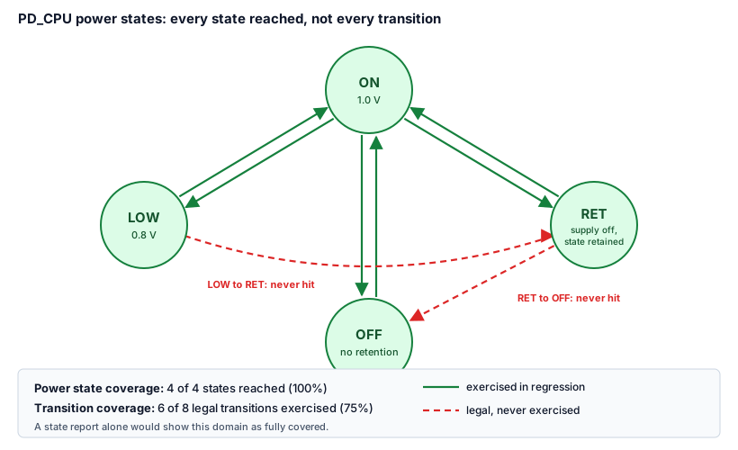
On top of both, cross coverage between multiple power domains and supply sets is what actually confirms the overlapping, multi-domain scenarios described earlier in this section were tested, rather than assumed. None of this replaces a pass/fail check - the assertions and scoreboard results still have to be clean - but a clean run with thin power state coverage just means the interesting transitions haven't been tried yet.
UPF (the Unified Power Format) is the industry-standard way power domains, isolation, retention, and switching are actually specified - it's a large enough topic on its own that it deserves dedicated reading. chipverify.com's UPF Design Flow and UPF Verification Strategies pages cover the syntax and flow this article assumes.
Where and When: RTL Versus Gate-Level Power-Aware Verification
Power-aware verification isn't a single pass done once. It runs at two distinct stages, against two different things, and both are necessary.
At RTL, before any real isolation, level-shifter, or retention cell physically exists, the UPF description is overlaid on the RTL as a set of placeholder power-aware models, and the same functional testbenches already built for ordinary verification are re-run with power-awareness turned on. This stage checks intent: does the UPF correctly describe which domains exist, which signals cross between them, and where isolation and retention are required. Catching a missing or misdirected isolation requirement here is cheap, because nothing has been synthesized yet - it's a shift-left benefit, reusing tests that already exist rather than writing new ones.
At gate level, after synthesis has inserted the real cells, the same kind of checking runs again, but against a fundamentally different artifact. The isolation, level-shifter, and retention cells are now real standard cells pulled from a library, each with its own power_down_function attribute defining exactly what that cell outputs when its power domain is off - and the hierarchy has typically been flattened, with signal and instance names that no longer match the RTL one-to-one. UPF has to be re-applied against this new structure, and the check now confirms implementation: that synthesis didn't drop a cell, swap a direction, or wire a clamp to the wrong constant, none of which the RTL-stage check could have seen, since none of those cells existed yet at that stage.
Because rewriting UPF from scratch for the gate-level netlist would risk losing coverage continuity between the two stages, teams generally aim for reusable UPF: a single UPF description written to survive both stages with little to no modification, so a domain, port, or strategy verified at RTL maps directly onto its gate-level equivalent instead of requiring a separate equivalence check between two independently-written specifications.
Common Mistakes
Waiting until gate-level, post-synthesis verification to check power intent.
By the time a power architecture bug is found at the gate level, fixing it is far more expensive than catching it at RTL with UPF-aware simulation, where the same power intent can be checked early and reused across the same testbenches already built for functional verification.
Assuming a signal is isolated because the UPF file says it should be.
The UPF specification states intent; it doesn't guarantee the RTL and the synthesized isolation cell actually match it. A missing or backwards isolation cell is a structural bug the design can have even with a perfectly correct UPF description, and needs its own dedicated check.
Only testing single, isolated power-down and power-up sequences one domain at a time.
Real chips power multiple domains up and down close together, and the bugs that matter most tend to live in the overlap - a wake-up arriving mid-sequence, or two domains transitioning at once - not in a single domain's clean, isolated transition.
Summary
In this article, you learned:
- Power domains create the same kind of cross-domain problem as clock and reset domains, with X-propagation in place of metastability
- Isolation cells, level shifters, retention registers, and power switches are the four structural elements power-aware verification checks for at every domain boundary
- A missing or misconfigured isolation cell lets X-values spread widely before they show up as a visible failure, which is why targeted assertions on the isolation and retention control signals catch the bug faster than waiting for a scoreboard
- Power sequencing verification has to check the full ordered transition - clock, isolation, retention, and power together - not just whether a domain eventually turns off and back on
- The bugs that matter most tend to live in overlapping, multi-domain transitions, not in a single domain's clean, isolated power-down and power-up
- Power-aware verification runs at both RTL and gate level, checking different things each time, and closes with power state and transition coverage rather than a single pass/fail result
